Annular combustion chambers for turbine engines
一种环形燃烧室、涡轮发动机的技术,应用在燃烧室、连续燃烧室、燃烧方法等方向,能够解决火焰周边蔓延困难、降低燃烧室性能等问题
- Summary
- Abstract
- Description
- Claims
- Application Information
AI Technical Summary
Problems solved by technology
Method used
Image

Examples
Embodiment Construction
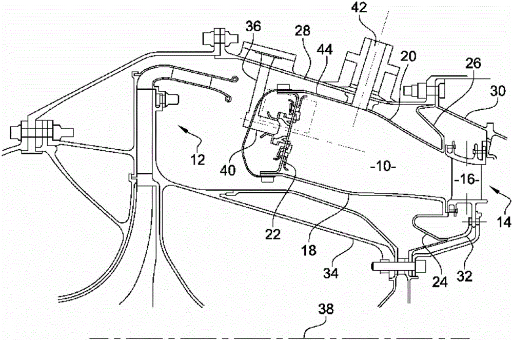
[0043] see first figure 1 , figure 1 An annular combustion chamber 10 of a turbine engine, such as a turboprop or turbojet, is shown at the outlet of a centrifugal diffuser 12 mounted at the outlet of a high pressure compressor (not shown). The combustion chamber 10 is followed by a high-pressure turbine 14 , of which only the intake nozzle 16 is shown.
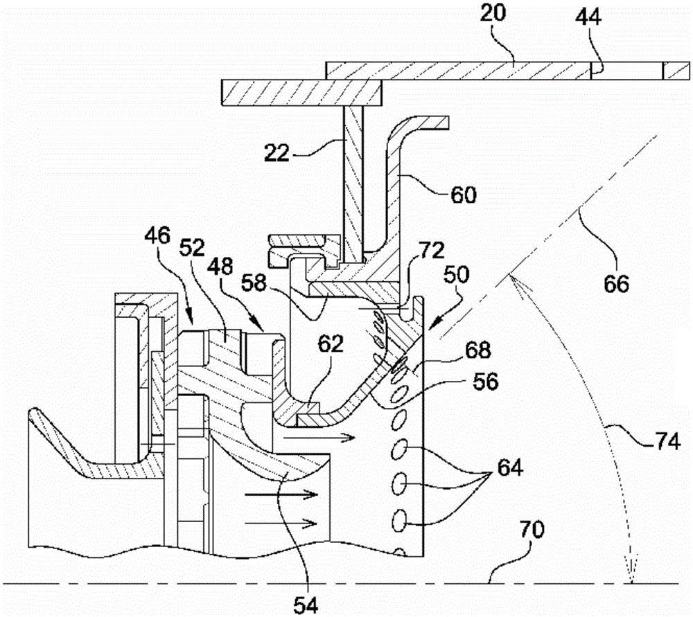
[0044]The combustion chamber 10 has coaxial inner and outer frusto-conical walls 18 and 20 forming surfaces of revolution nested one within the other and having a downwardly conical section. Such a combustion chamber is called converging. The inner and outer annular walls 18 and 20 are connected at their upstream ends to an annular chamber end wall 22 and they are secured downstream by inner and outer annular flanges 24 and 26 . The outer annular flange 26 bears radially outward against a housing 28 and axially against a radial flange 30 for fastening the nozzle 16 of the high-pressure turbine to the housing 28 . The inne...
PUM
 Abstract
Description
Claims
Application Information