
Novel storage cabinet rotating device

A technology of rotating device and storage cabinet, which is applied to rotating cabinets, cabinets, household appliances, etc., can solve the problems of increased cost input, single style, trouble in life, etc., and achieves ingenious structural design, easy and labor-saving rotation, and firm structural connection. Effect

Inactive Publication Date: 2014-06-11
ZHEJIANG LVLIN TECHNICS
View PDF0 Cites 3 Cited by
  • Summary
  • Abstract
  • Description
  • Claims
  • Application Information

AI Technical Summary

Problems solved by technology

With the continuous improvement of people's living standards, people will continue to buy items and use them for long-term accumulation. Many items cannot be placed centrally, which makes the room dirty and takes up space. It seems wasteful to throw them away. Therefore, lockers For families or dormitories with less space, it is a must-have item
Traditional lockers have a single structure and are basically a storage space. If you put multiple items in the cabinet together, it will be troublesome to search for the next time you use it, or put a locker for one type of item, every family needs Buying more lockers takes up space and increases cost. Several lockers are stacked together, and there is no rotating device between the two lockers. It is quite inconvenient to search for items or move the lockers, which brings great inconvenience to our life. come to trouble

Method used


Image

  • Novel storage cabinet rotating device
  • Novel storage cabinet rotating device
  • Novel storage cabinet rotating device

Examples


Embodiment Construction

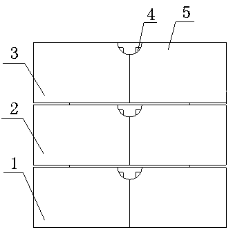
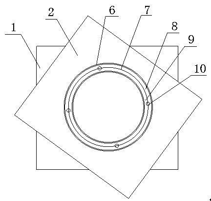
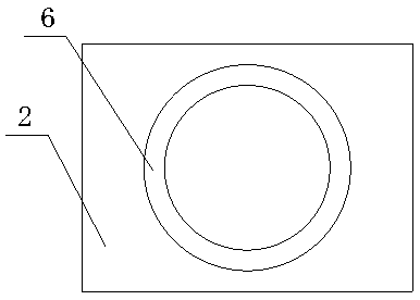
[0014] Such as figure 1 , 2 , 3, and 4, a new type of locker rotation device, including a first cabinet 1, a second cabinet 2, a third cabinet 3, a turntable 7, the top of the first cabinet 1 is provided with Groove 6, groove 6 is provided at the bottom of the third cabinet body 3, groove 6 is provided at the bottom and top of the second cabinet body 2, and a turntable is installed in the groove 6 at the top of the first cabinet body 1 and the second cabinet body 2 7. The second cabinet body 2 is inserted into the turntable 7 through the groove 6 and stacked on the first cabinet body 1. The third cabinet body 3 is inserted into the turntable 7 through the groove 6 and stacked on the second cabinet body 1. Each Both sides of the cabinet body are connected to the cabinet door 5 through hinges 11, and drawers 12 are provided in the cabinet cavity. The turntable 7 is composed of an outer turntable 8 and an inner turntable 9 , and the outer turntable 8 is connected to the inner t...


PUM


Abstract

The invention provides a novel storage cabinet rotating device, which comprises a first cabinet body, a second cabinet body, a third cabinet body and turntables, wherein a groove is formed in the top of the first cabinet body, a groove is formed at the bottom of the third cabinet body, the bottom and the top of the second cabinet body are respectively provided with grooves, the turntables are respectively arranged in the grooves formed in the tops of the first cabinet body and the second cabinet body, the second cabinet body is overlapped on the first cabinet body through clamping the turntables into the grooves, the third cabinet body is overlapped on the second cabinet body through clamping the turntable into the groove, the two sides of each cabinet body are connected with cabinet doors through hinges, and drawers are arranged in inner cavities of the cabinet bodies. The turntables consist of outer turntables and inner turntables, and the outer turntables are connected with the inner turntables through rolling balls. The novel storage cabinet rotating device has the advantages that the cabinet bodies can realize the free rotation through the turntables, the structural design is ingenious, articles can be conveniently found, the turntables are formed by connecting the inner turntables and the outer turntables through the rolling balls, the structure connection is firm, the rotation is easy and labor-saving, the cabinet bodies are connected with the cabinet doors through the hinges, the cover turning is free, circular arc-shaped notches are formed in the top corners of the cabinet doors, and the cabinet doors can be conveniently opened.

Description

technical field [0001] The invention relates to a furniture item, in particular to a new type of rotating device for a locker. Background technique [0002] The locker is a kind of daily furniture item, which is mainly used to facilitate people to store different items and classify them into categories. With the continuous improvement of people's living standards, people will continue to buy items and use them for long-term accumulation. Many items cannot be placed centrally, which makes the room dirty and takes up space. It seems wasteful to throw them away. Therefore, lockers For families or dormitories with less space, it is a must-have item. Traditional lockers have a single structure and are basically a storage space. If you put multiple items in the cabinet together, it will be troublesome to search for the next time you use it, or put a locker for one type of item, every family needs Buying more lockers takes up space and increases cost. Several lockers are stacked ...

Claims


Application Information

Patent Timeline
IPC IPC(8): A47B49/00
Inventor 陈晓东
Owner ZHEJIANG LVLIN TECHNICS
Learn More