A rotary plunger type straw granulator

A technology of rotating column and granulator, applied in the direction of die extrusion granulation, etc., can solve the problems of high humidity and pulverization requirements of raw materials, low service life and easy failure, affecting the efficiency of granulation work, etc. Short time, short start-up time, and the effect of avoiding traffic jams

Active Publication Date: 2016-10-05
天津市特斯达食品机械科技有限公司
View PDF6 Cites 0 Cited by
  • Summary
  • Abstract
  • Description
  • Claims
  • Application Information

AI Technical Summary

Problems solved by technology

The existing straw granulator is mainly a flat die rolling granulator or a ring die rolling granulator, which has low working efficiency, high energy consumption, high requirements on the humidity and crushing degree of raw materials, and has a low service life and is prone to failure
Patent application number 201020519186.9 and authorized announcement number CN201841002U propose a dual-mode mutual-extrusion straw granulator, which consists of two rolling dies, and each rolling die is evenly equipped with an extrusion head and a forming hole. The forming holes are arranged staggeredly. There are compression holes at the heads of the forming holes. The middle part of the rolling die is the discharge cavity, and a cutter is installed in the discharge cavity: the extrusion head of one rolling roll extends to the end of the other rolling roll. In the forming hole, the extrusion head of the other rolling roller extends back into the forming hole of this rolling roller. The double-mode mutual-pressing and inter-extruding straw pellet machine has low energy consumption, high efficiency and low requirements for raw materials. , but the die hole of the equipment is easy to block or material accumulates around the die, which affects the efficiency of granulation work, increases reactive power loss, and even causes shutdown, and cannot be opened quickly after shutdown, and there are many faults in use

Method used


Image

  • A rotary plunger type straw granulator
  • A rotary plunger type straw granulator
  • A rotary plunger type straw granulator

Examples


Embodiment Construction

[0027] The following will clearly and completely describe the technical solutions in the embodiments of the present invention with reference to the accompanying drawings in the embodiments of the present invention. Obviously, the described embodiments are only some, not all, embodiments of the present invention. Based on the embodiments of the present invention, all other embodiments obtained by persons of ordinary skill in the art without creative efforts fall within the protection scope of the present invention.

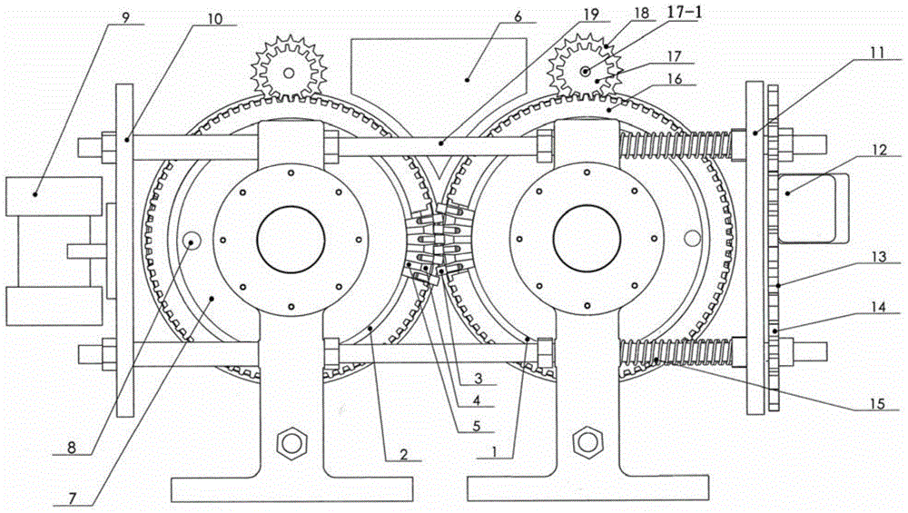
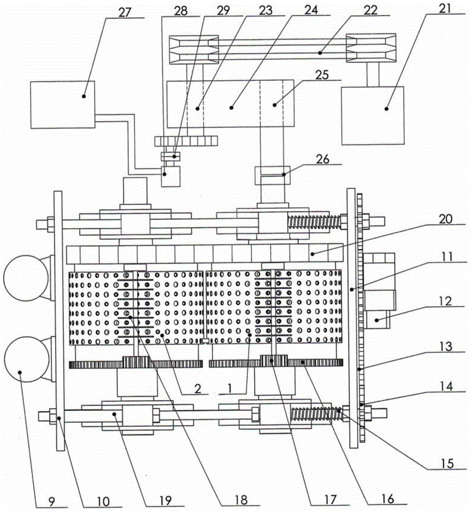
[0028] Such as figure 1 and figure 2 Commonly shown, a rotary plunger type straw granulator, including a first rolling die 1 and a second rolling die 2, the first rolling die 1 and the second rolling die 2 are provided with staggered Extruding head 3 and forming hole 5, the extruding head 3 on the first rolling die 1 stretches in the forming hole 5 on the second rolling die 2, and the extruding head 3 on the second rolling die 2 stretches toward In the forming h...


PUM


Abstract

The invention provides a rotary plunger type straw granulator. The rotary plunger type straw granulator comprises a first rolling die, a second rolling die, a charging chamber, discharging chambers, connecting rods and a mechanism, wherein material extruding heads and forming holes, which are of staggered arrangement, are formed in each of the first and second rolling dies, the material extruding heads on the first rolling die extend into the forming holes of the second rolling die, the material extruding heads on the second rolling die extend into the forming holes of the first rolling die, compression holes are formed in the heads of the forming holes, and the inside diameter of the compression holes is greater than or equal to the outside diameter of the material extruding heads and decreases gradually; cutters are arranged in the discharging chambers; the connecting rods are arranged between end faces of the same sides of the first and second rolling dies; the mechanism is used for increasing the extruding force of the material extruding heads. The rotary plunger type straw granulator has the beneficial effects that the work efficiency is high, the reactive power loss is low, and the like.

Description

technical field [0001] The invention relates to the technical field of agricultural equipment, in particular to a rotary plunger type straw granulator for extruding biomass such as straw, weeds and branches into granules. Background technique [0002] With the advancement of science and technology, in addition to direct accumulation and combustion of crop straw, people often process it into pellets to improve combustion efficiency and meet higher-level needs. The existing straw granulator is mainly a flat die rolling granulator or a ring die rolling granulator, which has low working efficiency, high energy consumption, high requirements on the humidity and crushing degree of raw materials, and has a low service life and is prone to failure . Patent application number 201020519186.9 and authorized announcement number CN201841002U propose a dual-mode mutual-extrusion straw granulator, which consists of two rolling dies, and each rolling die is evenly equipped with an extrusio...

Claims


Application Information

Patent Timeline
Patent Type & Authority Patents(China)
IPC IPC(8): B01J2/22
Inventor 刘德龙庄会永张秀艳董舰赵君
Owner 天津市特斯达食品机械科技有限公司
Why Eureka
Try Eureka