C pillar bottom connector structure
A joint structure and connecting plate technology, applied in the directions of superstructure, superstructure sub-assemblies, vehicle components, etc., can solve the problems of insufficient torsional stiffness and easy cracking, and achieve the effect of improving torsional stiffness and eliminating cracking defects.
- Summary
- Abstract
- Description
- Claims
- Application Information
AI Technical Summary
Problems solved by technology
Method used
Image
Examples
Embodiment Construction
[0021] The present invention will be further described below in conjunction with the accompanying drawings and specific embodiments.
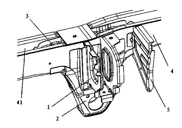
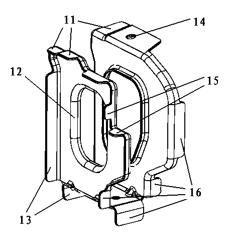
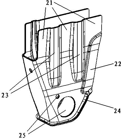
[0022] Figure 1 to Figure 5 The reference numerals in the figure are: middle rear support plate 1; first flange 11; third flange 12; second flange 13; installation belt installation hole 14; fourth flange 15; fifth flange 16; Spring front support 2; connecting plate 21; first rib 22; second rib 23; sixth flange 24; plate spring mounting hole 25; rear frame middle partition 3; lower flange 31; side flange 32 ; Horizontal reinforcement 33; Vertical reinforcement 34; Rear girder 4; Inner chamber 41; 54 ; raised portion 55 .
[0023] Such as Figure 1 to Figure 5 As shown, a C-pillar lower joint structure includes a central rear brace 1, a leaf spring front support 2, a rear frame middle partition 3, a rear frame 4 and a middle rear brace reinforcement plate 5, wherein the rear frame 4 is provided with an inner cavity 41, the middle partition ...
PUM
 Abstract
Description
Claims
Application Information
 - R&D
- Intellectual Property
- Life Sciences
- Materials
- Tech Scout
- Unparalleled Data Quality
- Higher Quality Content
- 60% Fewer Hallucinations
Browse by: Latest US Patents, China's latest patents, Technical Efficacy Thesaurus, Application Domain, Technology Topic, Popular Technical Reports.
© 2025 PatSnap. All rights reserved.Legal|Privacy policy|Modern Slavery Act Transparency Statement|Sitemap|About US| Contact US: help@patsnap.com


