Lighting device including interconnected parts

A light-emitting device and interconnection technology, applied in lighting devices, air-proof/waterproof devices, parts of lighting devices, etc., can solve problems such as high cost, and achieve the effect of saving materials and simple materials

Inactive Publication Date: 2014-06-11
LEDVANCE GMBH
View PDF9 Cites 63 Cited by
  • Summary
  • Abstract
  • Description
  • Claims
  • Application Information

AI Technical Summary

Problems solved by technology

All of these ancilla

Method used


Image

  • Lighting device including interconnected parts
  • Lighting device including interconnected parts
  • Lighting device including interconnected parts

Examples


Embodiment Construction

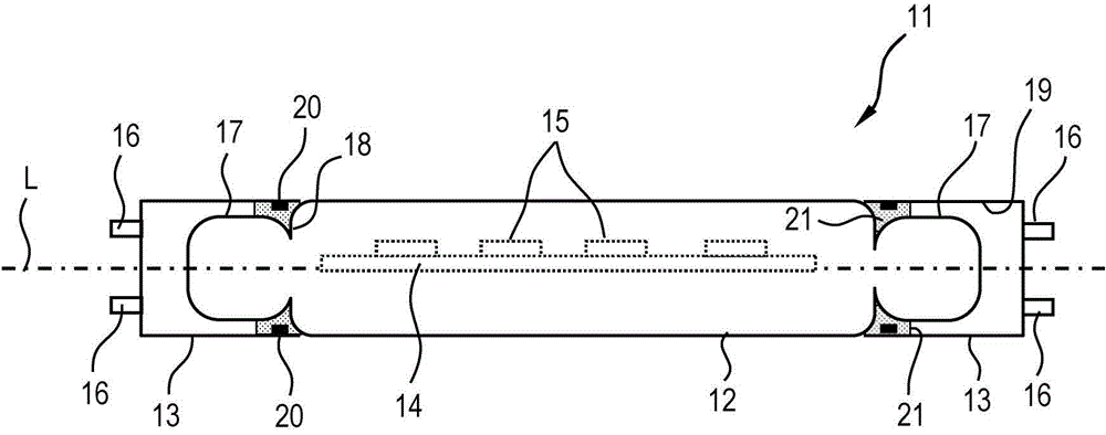
[0035] As a side sectional view, figure 1A tube lighting device 11 is shown, for example in the form of an LED retrofit lamp for replacing a fluorescent lamp or a tube lamp or the like. The luminous device 11 has a light-transmitting glass bulb 12 as a glass part with a cylindrical basic shape, cylindrical end caps 13 as a non-glass part, respectively mounted on the end regions of the glass parts . In the glass bulb 12 there is a circuit board 14 on which a plurality of light-emitting diodes 15 (shown in dashed lines) for generating light are arranged. The end cap 13 can consist, for example, of metal and / or plastic and has an electrical contact on the end side in the form of a contact pin 16 . A driver (not shown) for operating the light-emitting diodes 15 is arranged in one of the end caps 13 .

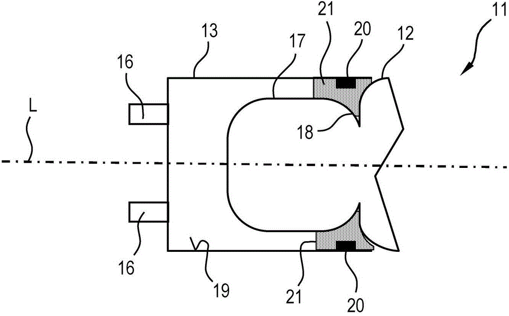
[0036] Such as figure 2 As shown enlarged in , the glass bulbs 12 each have an end region 17 on the end side with a reduced diameter for connection to the end cap 13 . The end...


PUM


Abstract

A lighting device (11) especially a semiconductor lighting device is provided. The lighting device may include at least one first part (12) and at least one second part (13), fastened to the first part (12), wherein the first and second parts are interconnected by a potting compound (21) especially a cured adhesive, the parts being positively interconnected by the potting compound (21).

Description

technical field [0001] The invention relates to a light-emitting device, especially a semiconductor light-emitting device, which has at least one first part, especially a glass part, and at least one second part, especially a non-glass part, fixed on the first part, the first part and the second part are connected to each other. connect. The invention can be applied in particular to retrofit lamps, especially LED retrofit lamps. Background technique [0002] In conventional and luminaires based on light-emitting diodes (LEDs) as light sources, glass parts are used, which have to be connected to non-glass parts according to function and design, e.g. glass bulbs with aluminum cooling body; glass tubes with end caps made of plastic, etc. Plastics, ceramics, and aluminum are often used as materials for non-glass parts. A known technique for making such a connection is to bond the oppositely arranged surfaces to each other with an adhesive or sealing material. The most danger...

Claims


Application Information

Patent Timeline
IPC IPC(8): F21V15/01F21K99/00
CPCF21V3/0418F21V19/002F21K9/175F21Y2101/02F21K9/90F21V31/04F21V19/00F21K9/1355F21V17/101F21K9/23F21Y2115/10F21K9/272F21V3/061
Inventor 托马斯·比特曼
Owner LEDVANCE GMBH
Why Eureka
Try Eureka