Position-measuring device

A measuring device, reflective measurement technology, applied in the direction of measuring device, using optical device to transfer sensing components, converting sensor output, etc., to achieve the effect of stable scanning signal, large installation tolerance, and easy installation

Active Publication Date: 2014-06-11
DR JOHANNES HEIDENHAIN GMBH
View PDF5 Cites 75 Cited by
  • Summary
  • Abstract
  • Description
  • Claims
  • Application Information

AI Technical Summary

Problems solved by technology

[0027] This consideration applies in principle only to flat gauges

Method used


Image

  • Position-measuring device
  • Position-measuring device
  • Position-measuring device

Examples


Embodiment Construction

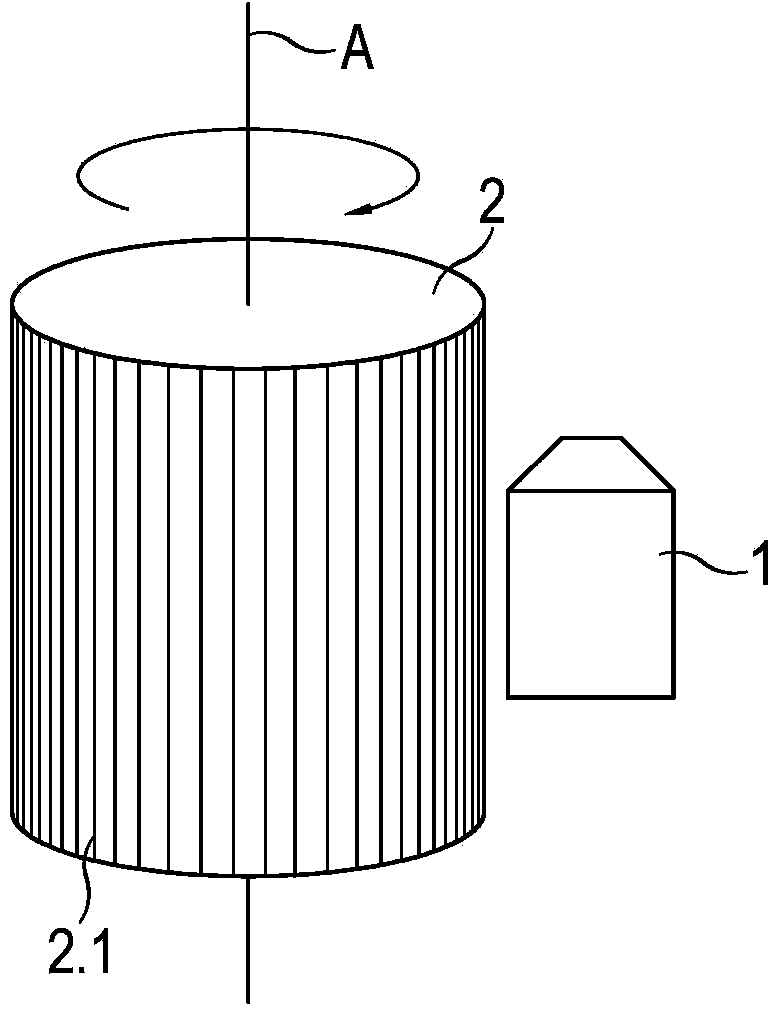
[0082] Figure 1a A greatly simplified spatial illustration of a first embodiment of the position-measuring device according to the invention is shown. The position-measuring device comprises, on the one hand, a cylindrical target 2 which is arranged rotatably about a longitudinal target axis A. FIG. On the target 2 , a ring-shaped reflective measurement scale 2.1 is provided as a gauge. On the other hand, stationary relative to the rotatably arranged target 1 , a scanning unit 1 is provided for optical scanning of the reflection measurement graduation 2 . 1 and thus for generating a rotation-dependent position signal. Scanning unit 1 is included in the Figure 1a Various components not shown in ; also belonging to this category are the light source, possible emission gratings and detectors.

[0083] Object 1 can be, for example, a rotating machine component. The position signal generated by the position-measuring device according to the invention is transmitted to—not sho...


PUM


Abstract

The present invention relates to a position-measuring device. The position-measuring device includes a cylindrical object rotatable about a longitudinal axis and comprising circumferential annular reflection measuring graduation; and a scanning unit which is static in relative to the object which is arranged in a rotatable manner, and used for optical scanning of reflection measuring graduation. The scanning unit includes a light source, a transmission grating and a detector. The light beam transmitted by the light source goes through the grating, and then is reflected to the reflection measuring graduation. Backward reflection along the direction of the detector is achieved through the reflection measuring graduation, and a position signal relating to rotation is generated by the light beam. An optically effective perpendicular distance between the detector and the reflection measuring graduation is selected to be one of greater or less than an optically effective perpendicular distance between the transmission grating and the reflection measuring graduation depending on a radius of the cylindrical object.

Description

technical field [0001] The invention relates to a position-measuring device according to the preamble of claim 1 . Background technique [0002] Such a position measuring device is known, for example, from the introduction to the description of EP 1 795 872 A1. FIG. 1 of this publication shows a position-measuring device which, on the one hand, has a cylindrical target with a circularly surrounding reflectance measurement graduation, wherein the target is arranged rotatably about its longitudinal axis. On the other hand, a scanning unit is provided that is stationary relative to the rotatable target for optical scanning of reflection measurement graduations. exist figure 2 B and figure 2 A scanning unit suitable for such a device is schematically shown in C and includes a light source, an emission grating and a detector, respectively. The light beam emitted by the light source passes through the transmission grating and then strikes the reflectance measurement scale. Th...

Claims


Application Information

Patent Timeline
Patent Type & Authority Applications(China)
IPC IPC(8): G01D5/34
CPCG01D5/3473G01D5/38G01D5/34715
Inventor 沃尔夫冈·霍尔扎普费尔米夏埃尔·赫尔曼卡斯滕·萨恩迪格
Owner DR JOHANNES HEIDENHAIN GMBH
Why Eureka
Try Eureka