Supercharge Your Innovation With Domain-Expert AI Agents!

Light attenuation control circuit

A light attenuation control and circuit technology, applied in the field of lighting, can solve the problem of not setting measures to detect the brightness of LED lamps and other problems

Active Publication Date: 2014-06-11
GUANGDONG RAYTON INTELLIGENT OPTO CO LTD
View PDF4 Cites 0 Cited by
  • Summary
  • Abstract
  • Description
  • Claims
  • Application Information

AI Technical Summary

Problems solved by technology

However, in the prior art, there is no measure for detecting the brightness of LED lamps to remind users to replace related lighting lamps

Method used


Image

  • Light attenuation control circuit

Examples


Embodiment Construction

[0010] A specific embodiment of the present invention will be described in detail below in conjunction with the accompanying drawings.

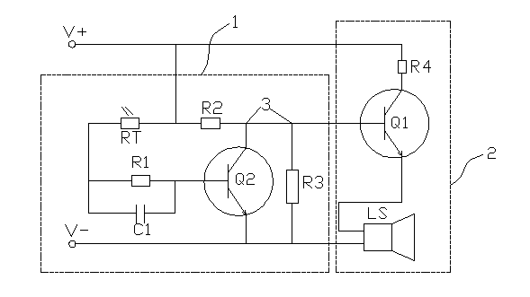
[0011] Such as figure 1 Shown is a specific embodiment of the light attenuation control circuit of the present invention, which includes a detection circuit 1 and an alarm circuit 2 .

[0012] The detection circuit 1 includes a photoresistor RT, a resistor R1, a resistor R2, a resistor R3, a capacitor C1 and a transistor Q2. One end of the photoresistor RT is connected to the positive pole of the power supply, and the other end is electrically connected to the base of the transistor Q2; after the capacitor C1 is connected in parallel to both ends of the resistor R1, they are connected to the base of the transistor Q2 together, and the capacitor C1 and the resistor R1 is located between the photoresistor RT and the base of transistor Q2; the collector of transistor Q2 is electrically connected to the positive pole of the power supply through ...


PUM


Abstract

The invention relates to the lighting field, in particular to a light attenuation control circuit of a lighting lamp. The light attenuation control circuit comprises a detection circuit and an alarm circuit electrically connected with the detection circuit. The detection circuit is mainly composed of a photoresistor, a transistor and multiple resistors. One end of the photoresistor is electrically connected to a base electrode of the transistor, the other end of the photoresistor is electrically connected to a positive electrode of a power source, a collector electrode of the transistor and one resistor are in series connection with the positive electrode of the power source, and one resistor is in parallel connection between the collector electrode and an emitting electrode of the transistor. The alarm circuit is mainly composed of an alarm and the transistor. The emitting electrode of the transistor is electrically connected to the alarm, the collector electrode of the transistor is electrically connected to the positive electrode of the power source, and the base electrode of the transistor is electrically connected to the detection circuit. Detection results of the detection circuit control the transistor in the alarm circuit to be switched on and switched off, so that alarm sound is controlled to be produced by the alarm, and the purpose that a user is reminded to replace the lamp is achieved.

Description

technical field [0001] The invention relates to the lighting field, in particular to a light attenuation control circuit of a lighting fixture. Background technique [0002] LED has the advantages of small size, low energy consumption, long service life, high brightness, etc., and is more and more widely used in the field of lighting. The theoretical service life of the LED is about 100,000 hours, but due to the light decay of the LED, its actual service life is 50,000 to 100,000 hours. [0003] During the use of LED lamps, its brightness gradually decreases with the light decay of LEDs. When the brightness of LED lamps decreases to the minimum brightness requirement for brightness in the lighting field, it is necessary to replace the lamps, otherwise it will affect people's normal life. . However, in the prior art, there is no measure for detecting the brightness of LED lamps to remind users to replace related lighting lamps. Contents of the invention [0004] Aiming a...

Claims


Application Information

Patent Timeline
Patent Type & Authority Applications(China)
IPC IPC(8): G01J1/44
Inventor 陈焕杰杨青
Owner GUANGDONG RAYTON INTELLIGENT OPTO CO LTD
Features
  • R&D
  • Intellectual Property
  • Life Sciences
  • Materials
  • Tech Scout
  • Unparalleled Data Quality
  • Higher Quality Content
  • 60% Fewer Hallucinations
Learn More