Contraposition method and optical device

一种光学装置、光束的技术,应用在光学、光学元件、测量装置等方向,能够解决治具调整程序复杂、激光光源散热不佳、生产成本高等问题,达到简化光学对位的过程、良好对位精度、减少治具的效果

Inactive Publication Date: 2014-06-11
LITE ON ELECTRONICS (GUANGZHOU) LTD +1
View PDF3 Cites 3 Cited by
  • Summary
  • Abstract
  • Description
  • Claims
  • Application Information

AI Technical Summary

Problems solved by technology

However, adjusting the optical axes of multiple laser light sources involves multiple degrees of freedom, so the required jigs and adjustment procedures are too complicated to be mass-produced, and the production cost is also high
At the same time, as the size and distance of the projection screen become larger and larger, the laser light source with increased power is also prone to poor heat dissipation and overheating.

Method used


Image

  • Contraposition method and optical device
  • Contraposition method and optical device
  • Contraposition method and optical device

Examples


Embodiment Construction

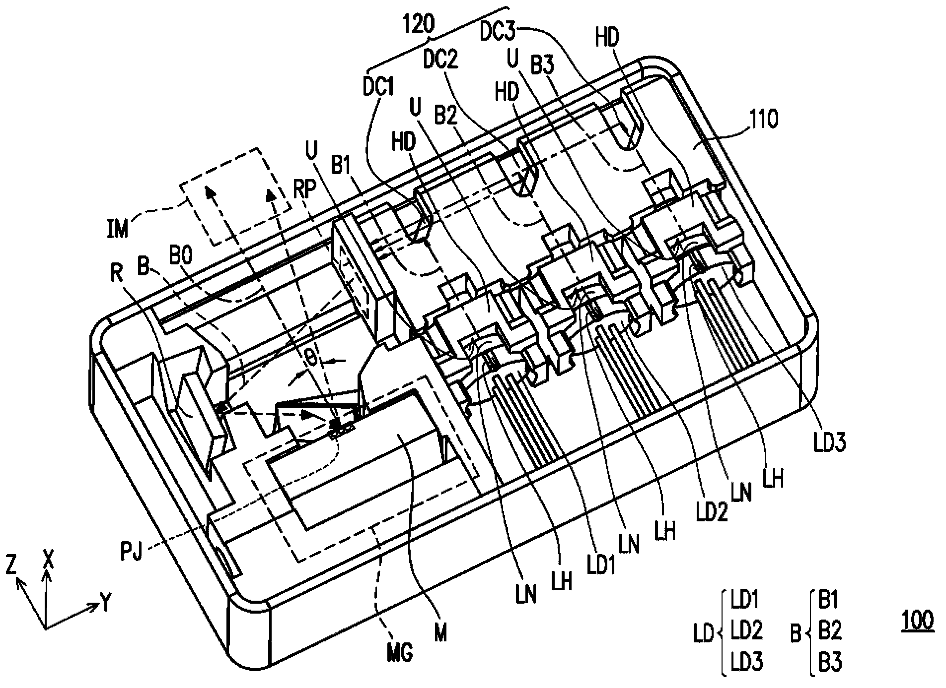
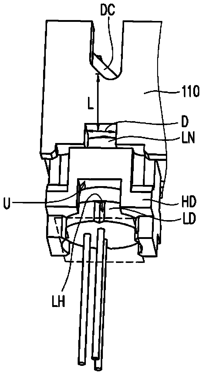
[0054] figure 1 is a schematic diagram of an optical device according to an embodiment of the present invention, figure 2 is according to figure 1 For a partially enlarged view of the optical setup in , please refer to figure 1 and figure 2, in this embodiment, the optical device 100 may include a fixing base 110, a plurality of lenses LN, a light combining unit 120, a plurality of light emitting elements LD and a plurality of holders HD. Wherein, the lens LN and the light combining unit 120 are fixed on the fixing base 110 . In this embodiment, the number of light-emitting elements LD is, for example, three, and the light-emitting elements LD can be laser diodes (laser diodes), but the present invention is not limited thereto, and in other embodiments, there can also be different numbers of The light emitting element LD, and the light emitting element LD can also be other elements such as light emitting diode (light emitting diode, LED). In this embodiment, the light e...


PUM


Abstract

The invention discloses a contraposition method and an optical device. The contraposition method comprises the steps that a plurality of lenses and a light combination unit are fixed in a fixed base; a plurality of light-emitting elements are arranged in a plurality of clampers respectively, so that the clampers abut against the fixed base, and the light-emitting elements are allowed to correspond to the lenses in position respectively; the light-emitting elements are turned on, and light beams are combined by the light combination unit after being emitted from the light-emitting elements respectively and penetrating through the lenses; at least part of the light-emitting elements are clamped through jigs respectively so that the positions of the clamped light-emitting elements can be respectively adjusted until the coincidence degree of the light beams combined by the light combination unit meets a preset requirement. In addition, the invention further discloses the optical device.

Description

technical field [0001] The invention relates to an alignment method and an optical device. Background technique [0002] In recent years, with the gradual increase in consumer demand for portable audio-visual devices, projection systems have been trending toward miniaturization. Among them, the pico-projector technology further reduces the size of the projection system, and thus has great market potential. Micro-electromechanical systems (MEMS) using laser light sources in micro-projection technology have the advantages of high image brightness, small size, and less limited projection distance, so they can be applied to portable products such as mobile phones, Notebook computer (laptop), tablet computer (tablet computer), camera, video recorder, portable media player (portable media player, PMP) and other products. However, due to the small size of the micro-projector, it is necessary to adjust the optical path in a limited space so that the beams of multiple laser light s...

Claims


Application Information

Patent Timeline
Patent Type & Authority Applications(China)
IPC IPC(8): G02B7/02G02B26/10G02B27/10
CPCG03B21/2013G01M11/00G02F1/00G03B43/00G03B21/2046
Inventor 林威志吕志坚林孟哲李权林家园许正忠林善雄
Owner LITE ON ELECTRONICS (GUANGZHOU) LTD
Why Eureka
Try Eureka