Optical fiber-type optical functional element cartridge module

A technology of optical functions and optical components, applied in the directions of optical components, optics, electrical components, etc., can solve the problems such as the inability to amplify the optical signal, and the optical coupling cannot be obtained by the optical fiber collimator.

Active Publication Date: 2014-06-11
NAT INST OF INFORMATION & COMM TECH
View PDF6 Cites 0 Cited by
  • Summary
  • Abstract
  • Description
  • Claims
  • Application Information

AI Technical Summary

Problems solved by technology

However, when an optical fiber type module or a waveguide type module is to be installed in the component box of the module disclosed in Japanese Invention Patent Publication No. 3933967 (patent document) 1, there will be a gap between the optical fiber collimators positioned at both ends of the module. The problem of not getting good optical coupling between
[0005] In the existing optical functional element box module, there is also the problem that the optical signal cannot be amplified

Method used


Image

  • Optical fiber-type optical functional element cartridge module
  • Optical fiber-type optical functional element cartridge module
  • Optical fiber-type optical functional element cartridge module

Examples


Embodiment Construction

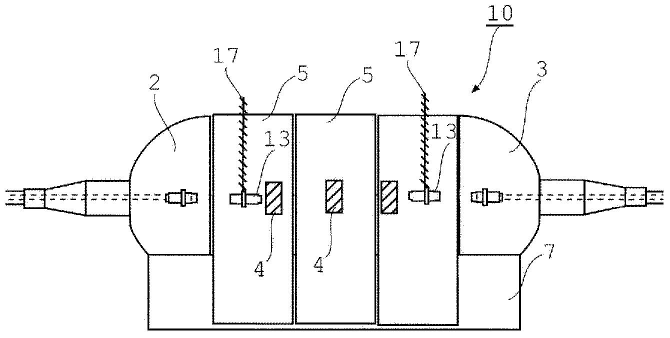
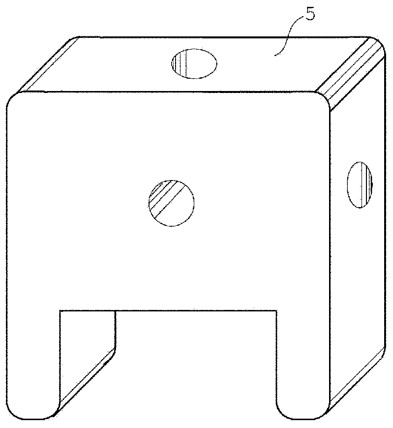
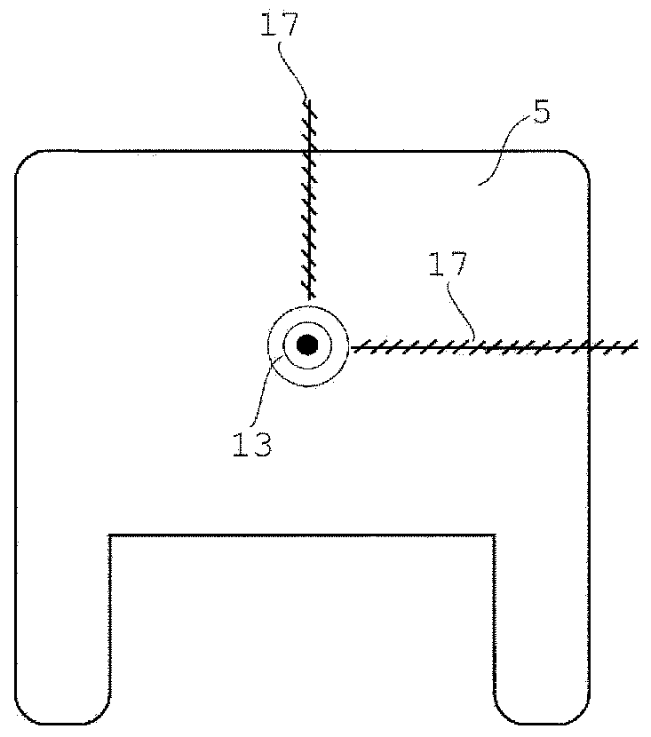
[0021] In the present invention, at least the component boxes located at both ends of the module have collimators. In addition, the present invention, for example, improves the component box to allow fine adjustment of the position of the collimator. A collimator insertion portion is provided at the center of the component box, and an adjustment mechanism is provided in a hole located above it and a hole extending in a lateral direction. Therefore, when the module is actually set up, after installing multiple component boxes on the substrate, the position of the collimator can be adjusted so that the optical coupling of each component box and the optical coupling of the fiber collimator can reach the best state. The adjustment mechanism is, for example, a screw that can be manually operated to move, or an actuator (Actuator) that can move a position by an electric command. The position of the collimator can be optimized by this adjustment mechanism, so even if a fiber-type or...


PUM


Abstract

The invention provides a cartridge-type optical functional module, which can achieve excellent optical coupling and has an optical fiber-type module or a waveguide-type module. The present invention relates to a cartridge-type optical functional module (10) which has: first and second optical fiber collimators (2, 3); an optical functional object (5) which has an optical fiber-type module or a waveguide-type module; and a base section (7). The optical functional object (5) has a third collimator (13), and a first position adjusting mechanism (17) for adjusting the position of the third collimator (13) in the optical functional object (5).

Description

technical field [0001] The invention relates to a fiber optic functional element box module. Background technique [0002] An optical functional element box module is disclosed in Japanese Patent Publication No. 3933967 (Patent Document 1). The box-type optical functional module disclosed in this document targets bulk type optical functional components. [0003] [Patent Document 1] Japanese Invention Patent Publication No. 3933967 [0004] In addition, there is a need in the prior art for modules using optical elements other than bulk optical elements. However, when an optical fiber type module or a waveguide type module is to be installed in the component box of the module disclosed in Japanese Invention Patent Publication No. 3933967 (patent document) 1, there will be a gap between the optical fiber collimators positioned at both ends of the module. The problem of not getting good optical coupling between them. [0005] In the existing optical functional element box mo...

Claims


Application Information

Patent Timeline
Patent Type & Authority Applications(China)
IPC IPC(8): G02B6/32G02B6/00H01S3/067H01S3/10
CPCG02B6/26G02B6/32G02B6/3616G02B6/264
Inventor 和田尚也小林哲也鸟取裕作
Owner NAT INST OF INFORMATION & COMM TECH
Why Eureka
Try Eureka