Sawing machine clamp

A fixture and sawing machine technology, which is applied in the field of fixtures, can solve the problems of difficult inspection and maintenance, lower production efficiency, and easy to cause work-related injuries, so as to avoid manual pressing, improve work efficiency, and ensure life safety.

Active Publication Date: 2014-06-18
WANSHITAI METAL IND KUNSHAN
View PDF8 Cites 24 Cited by
  • Summary
  • Abstract
  • Description
  • Claims
  • Application Information

AI Technical Summary

Problems solved by technology

The sawing machine includes the sawing machine fixture, and the sawing machine fixture includes the positioning fixture and the feeding fixture. The existing sawing machine positioning fixture generally uses manual force to clamp the material. For the positioning fixture of the sawing machine used for positioning large materials, this is not only time-consuming and laborious. Reduced production efficiency, but also prone to work-related injuries
In addition, the device for cutting materials is generally located under the positioning fixture. When there is a problem with the device for cutting materials and needs to be inspected and repaired, due to the blocking effect of the positioning device, inspection and maintenance become difficult.

Method used


Image

  • Sawing machine clamp
  • Sawing machine clamp
  • Sawing machine clamp

Examples


Embodiment 1

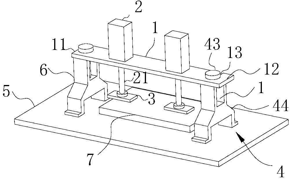
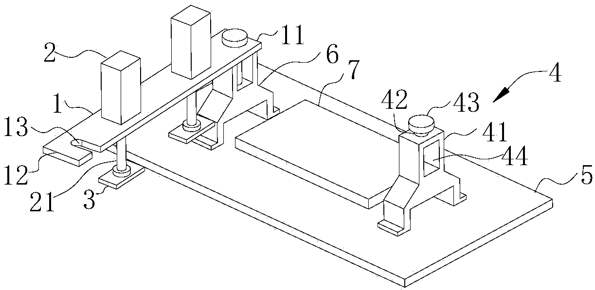
[0026] Such as Figure 1~2 As shown, in this embodiment, a kind of sawing machine clamp described in the present invention comprises the rotating crossbeam 1 that is arranged on the top of workbench 5, and rotating crossbeam 1 comprises hinged end 11 and free end 12, and the hinged end 11 of rotating beam 1 The first fixing device 6 hinged with the rotating beam 1 is arranged below, and the second fixing device 4 that can fix the end is arranged below the free end 12 of the rotating beam 1, and the first fixing device 6 and the second fixing device 4 can be disassembled fixed on the workbench 5, and at least one pressing device is arranged on the rotating beam 1 along its length direction for automatically pressing the materials 7 placed on the workbench 5.

[0027] By setting the rotating beam 1, when the staff needs to check or clean the cutting material device, they only need to separate the free end of the rotating beam 1 from the first fixing device 6, and then rotate the...

Embodiment 2

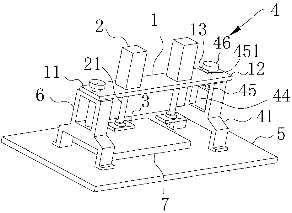
[0038] Such as image 3As shown, the difference between this embodiment and Embodiment 1 is only that the fixing member is a power compression mechanism, and the power compression mechanism includes a power device 45 and a pressing block 46, and the power device 45 is fixed in the cavity 44 near the workbench 5. On the side, the briquetting block 46 is arranged on the side of the fixed block 41 away from the workbench 5, the power unit 45 has an output shaft 451, and the end of the output shaft 451 passes through the fixed block 41 and is connected with the briquetting block 46 for driving the briquetting block 46 Press the rotating beam 1, and the rotating beam 1 is provided with a clamping hole 13 for the output shaft 451 to pass through. The clamping hole 13 has an opening through which the output shaft 451 can pass.

[0039] By setting the fixing member as a power pressing mechanism, after the free end 12 of the rotating beam 1 is clamped, the pressure block 46 can be comp...


PUM


Abstract

The invention discloses a sawing machine clamp. The sawing machine clamp comprises a rotating cross beam arranged above a worktable, wherein the rotating cross beam comprises a hinging end and a free end, a first fixing device which is hinged to the rotating cross beam is arranged under the hinging end of the rotating cross beam, a second fixing device capable of fixing the free end is arranged under the free end of the rotating cross beam, both the first fixing device and the second fixing device can be detachably fixed on the worktable, and the rotating cross beam is provided with at least one material-pressing device used for automatically pressing materials placed on the worktable in the length direction of the rotating cross beam. Through the arranged rotating cross beam, when a material cutting device needs to be checked, unimpeded check can be achieved by rotating the rotating cross beam, and further the rotating cross beam brings convenience to carrying of the materials. Besides, through the arranged material-pressing device, the sawing machine clamp can achieve material pressing without handwork, improve work efficiency, reduce industrial accidents and guarantee life safety of workers.

Description

technical field [0001] The invention relates to the field of clamps, in particular to a sawing machine clamp. Background technique [0002] With the development of modern manufacturing industry towards high efficiency, high precision and economy, sawing, as the starting point of precision cutting, has become an important part of the process of parts processing. Sawing can save materials, reduce secondary processing and improve production efficiency, so sawing machines, especially automated sawing machines, have been widely used in steel, machinery, automobiles, shipbuilding, petroleum, mining and aviation and other fields. The sawing machine includes the sawing machine fixture, and the sawing machine fixture includes the positioning fixture and the feeding fixture. The existing sawing machine positioning fixture generally clamps the material by manual force. For the positioning fixture of the sawing machine used for positioning large materials, it is not only time-consuming ...

Claims


Application Information

Patent Timeline
Patent Type & Authority Applications(China)
IPC IPC(8): B23Q3/08
CPCB23Q3/069B23Q3/082B23Q2703/04
Inventor 林进光
Owner WANSHITAI METAL IND KUNSHAN
Why Eureka
Try Eureka