
Hub type energy-saving vibration-reducing pneumatic power generating device

A technology of power generation device and pneumatic generator, which is applied in the direction of auxiliary drive device, control device, transportation and packaging, etc. It can solve the problems of difficult sealing process at the interface, space occupation of wheel hub, space occupation of wheel hub, etc., to achieve saving The effect of dropping the power generation network network, facilitating process realization, and working balanced and stable

Active Publication Date: 2014-06-18
湖南亿尚清洁工程有限公司
View PDF8 Cites 1 Cited by
  • Summary
  • Abstract
  • Description
  • Claims
  • Application Information

AI Technical Summary

Problems solved by technology

[0008] In the above technical scheme, a connecting pipe is provided between the adjacent two inner tubes, which is not convenient for technical realization, and the sealing process at the interface is difficult; at the same time, the vibration during movement will affect the connection between the adjacent two inner tubes; in addition, its Multiple pneumatic generators need to be set up during work, and the electric energy network network generated by power generation is complex; and it will inevitably occupy the space of the wheel hub, which will bring difficulties to the manufacture of the wheel hub. At the same time, the occupied space of the wheel hub will inevitably lead to a decrease in the integrity , the stiffness of the hub will inevitably be affected by

Method used


Image

  • Hub type energy-saving vibration-reducing pneumatic power generating device
  • Hub type energy-saving vibration-reducing pneumatic power generating device

Examples


Embodiment Construction

[0025] In order to enable those skilled in the art to better understand the technical solution of the present invention, the present invention will be described in detail below in conjunction with the accompanying drawings. The description in this part is only exemplary and explanatory, and should not have any limiting effect on the protection scope of the present invention. .

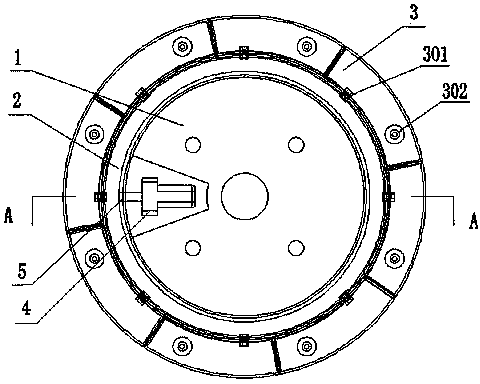
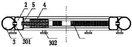
[0026] Such as Figure 1-2 As shown, the connection relationship of the present invention is: it includes wheel hub 1, compressed air bag 3 and pneumatic generator 4, and the outer periphery of described wheel hub 1 is connected with annular gas collection tank 2; There are at least two compressed air bags 3; The compressed air bags 3 are evenly distributed on the outer periphery of the gas collection tank 2, and the compressed air bags 3 are separated from each other; the compressed air bags 3 communicate with the gas collection tank 2 through a valve 301, and the compressed air An air intake valve 3...


PUM


Abstract

The invention discloses a hub type energy-saving vibration-reducing pneumatic power generating device, comprising a hub, at least two compressed air bags and a pneumatic generator, wherein the periphery of the hub is connected with an annular air collector, the compressed air bags are uniformly distributed at the periphery of the air collector, and are isolated from each other, the compressed air bags are communicated with the air collector through valves, the outer sides of the compressed air bags are provided with air inlet valves, the radial direction of the hub is provided with the pneumatic generator, and the pneumatic generator is communicated with the air collector through air hole connecting parts. The invention aims to provide the energy-saving hub vibration-reducing pneumatic power generating device, which is used for converting vibration in vehicle movement and partial energy generated by self weight, electric energy generated through the power generating device is charged into a storage battery of the vehicle, so that the service life of the storage battery is prolonged, and the working time of electric car series is greatly prolonged. The hub type energy-saving vibration-reducing pneumatic power generating device is simple and reliable in structure and has a small influence on the rigidity of the hub.

Description

technical field [0001] The invention belongs to the field of vehicle manufacturing and power generation, and relates to a hub-type energy-saving and vibration-reducing pneumatic power generation device, in particular to a device which is arranged on the hub of a wheel to reduce vehicle vibration and utilizes vibration and vehicle self-weight to generate power through inner tube compressed air . Background technique [0002] Automobile is an indispensable means of transportation in modern transportation, and its use has almost reached the level of global popularity, playing an important role in modern life. The progress of the car is mainly driven by the generator to drive the wheels forward. The wheels are mainly composed of the hub and the inner tube and outer tube surrounded by the hub. The inner tube is filled with a certain pressure of gas, which can slow down the bumps and vibrations caused by uneven road surfaces. [0003] In the existing vehicle technology, the use o...

Claims


Application Information

Patent Timeline
Patent Type & Authority Applications(China)
IPC IPC(8): B60K25/08
Inventor 杨迪军
Owner 湖南亿尚清洁工程有限公司
Learn More