Vibration dampened drilling tool

A technology of drill bit and drill body, which is applied in the direction of shock absorber, friction shock absorber, drill repairing, etc., and can solve the problem of not being able to give noise

Inactive Publication Date: 2003-08-20
SANDVIK INTELLECTUAL PROPERTY AB
View PDF0 Cites 7 Cited by
  • Summary
  • Abstract
  • Description
  • Claims
  • Application Information

AI Technical Summary

Problems solved by technology

However, the hard metal border imposed according to patent 8902081-2 still does not give a suitably quiet noise

Method used


Image

  • Vibration dampened drilling tool
  • Vibration dampened drilling tool
  • Vibration dampened drilling tool

Examples


Embodiment Construction

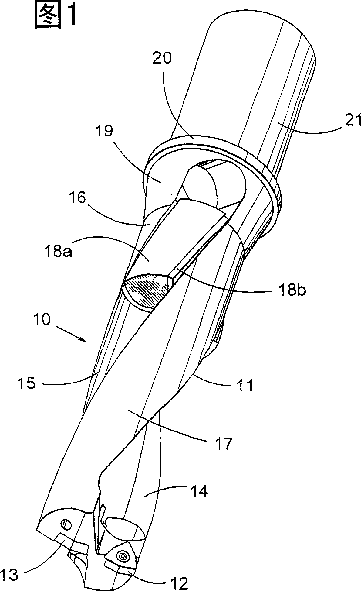
[0010] According to the invention shown in FIG. 1, the embodiment of the drill bit portion 10 containing the damping elements 18a and 18b includes a drill body 11, and an outer cutting insert 12 at the edge of the drill bit and an inner cutting insert 13 near the center of the drill bit. The cutting insert is preferably made of cemented carbide. The two cutting inserts are located at different radial distances from the drill axis A, and their operating areas overlap each other. At the same time, the two cutting blades are offset by about 180° in the circumferential direction of the drill. The cutting inserts 12, 13 are fastened in corresponding insert seats on the drill body 11 in a known manner, such as a threaded connection. The drill body 11 has a substantially cylindrical basic shape and is made of steel.

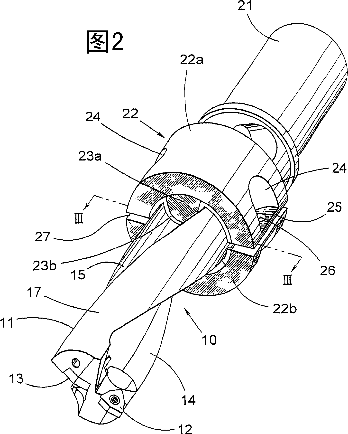
[0011] On the part of the drill body 11 located behind the cutting blade, there are provided grooves 14, 15 extending axially and opening radially outward. The cross sectio...


PUM


Abstract

A drilling tool includes a drill body having chip channel formed therein and carrying cutting inserts at front ends of respective chip channels. Disposed in the chip channels at a location spaced from the cutting insert are respective damping elements. Each damping element comprises first and second portions formed of respective materials of different rigidity.

Description

Technical field [0001] The invention relates to a drill bit used for metal material processing. In particular, it relates to a drill bit whose drill body is provided with at least one insert cutting blade for forming the peripheral contour of the hole, one or more grooves are formed along the longitudinal direction of the drill bit, and the grooves are respectively connected with the inner and outer inserts. The blades are connected and used as chip flutes. Background technique [0002] When drilling metal materials, there will be a problem of high noise caused by vibration of the workpiece and the machine. The drill bits used so far are not equipped with built-in / external vibration damping devices to obtain suitable sound and dampen vibration. The key problem is to be able to basically eliminate the vibration sound in the range that is uncomfortable to human ears. Where possible, only machine noises in the range of 74-76 decibels and the inevitable chip breaking sound are allowe...

Claims


Application Information

Patent Timeline
Patent Type & Authority Applications(China)
IPC IPC(8): B23Q11/00B23B51/00B23B51/04F16F7/08F16F7/108F16F15/04F16F15/08
CPCF16F7/08B23B2250/16F16F15/08B23B51/048F16F7/108F16F15/04Y10T408/76Y10T409/304312B23B51/00
Inventor 马里-路易丝·贝霍尔特莱夫·卡尔松汤米·图卡拉
Owner SANDVIK INTELLECTUAL PROPERTY AB
Why Eureka
Try Eureka