Eye protecting and illuminating device used in computer using process

A computer and control circuit technology, applied in the field of display equipment, can solve the problems of eye injury and poor eye protection effect, and achieve the effects of uniform lighting, better lighting effect, and increased effective irradiation surface

Active Publication Date: 2014-06-18
TIANJIN MINGDAOHUISHI TECH
View PDF10 Cites 3 Cited by
  • Summary
  • Abstract
  • Description
  • Claims
  • Application Information

AI Technical Summary

Problems solved by technology

[0004] The problem to be solved by the present invention is to provide an eye protection and lighting device when using a computer, which can realize eye protection while using the eyes, solve the problem that the existing computer eye protection device has poor eye protection effect, and even hurts the eyes, and provide Computer with keyboard and peripheral lighting

Method used


Image

  • Eye protecting and illuminating device used in computer using process
  • Eye protecting and illuminating device used in computer using process
  • Eye protecting and illuminating device used in computer using process

Examples


Embodiment 1

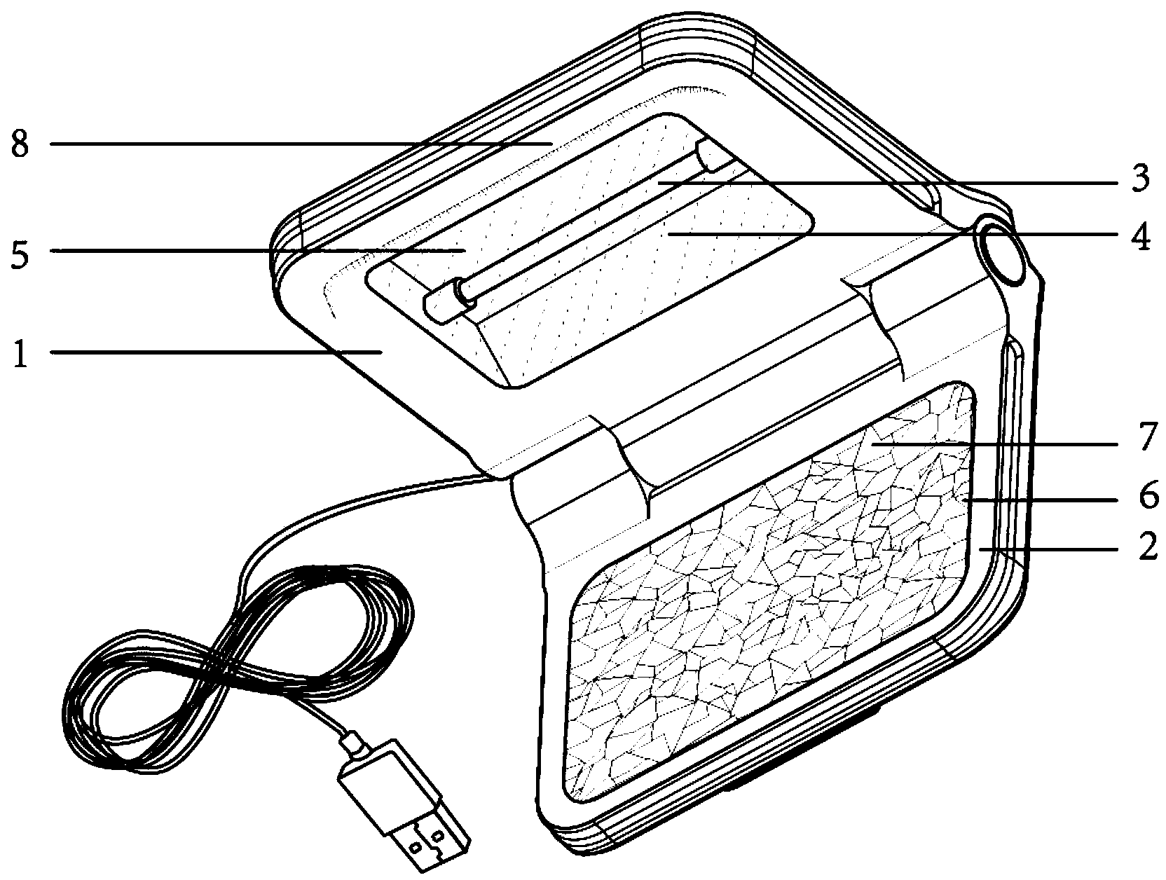
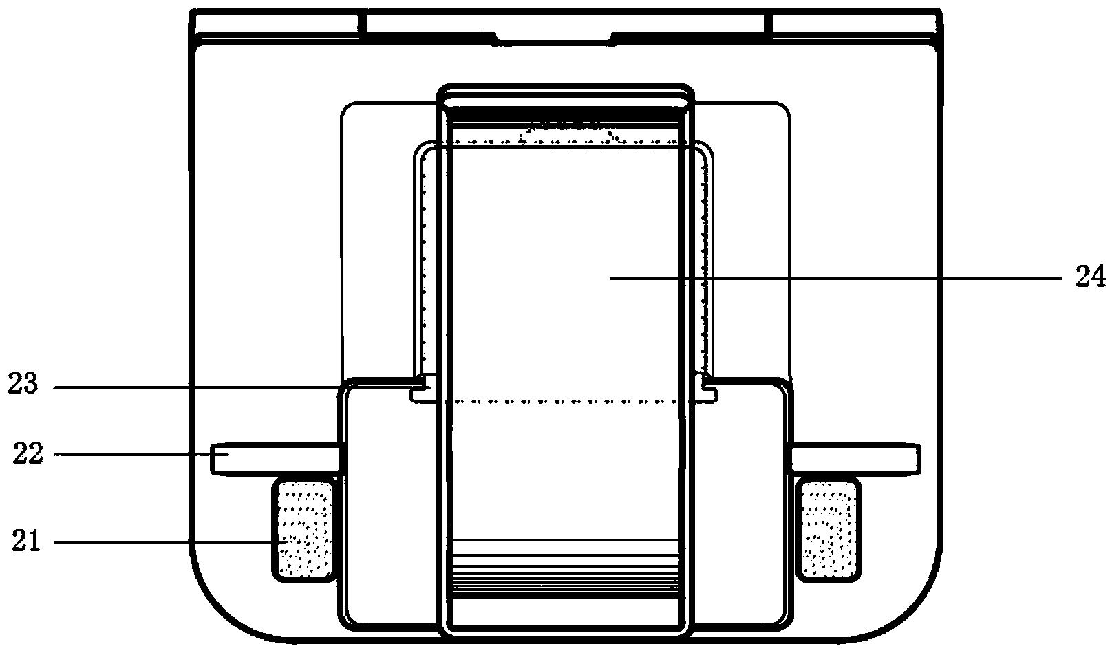
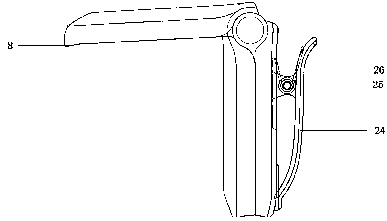
[0050] Embodiment 1: as figure 1 As shown, a device for eye protection and lighting when using a computer, including a light source part 1 and a low-light reflection part 2, the two are movably connected by a hinge assembly and the angle between the two can be kept at any angle within the range of 0 to 90 degrees. An angle; a linear light source 3 is provided on the light source part 1, and an eye protection spectrum card 6 is provided on the low-light reflection part 2; a clamping mechanism is provided at the rear end of the low-light reflection part 2; a control circuit is also included for Control the start and work of the light source.

[0051] The light source component 1 includes a reflector 4, a linear light source 3 and a diffuse transmission sheet 5 arranged in sequence along the vertical direction; the linear light source 3 is a cold cathode lamp tube; the cold cathode lamp tube is connected to the output end of the control circuit, and the input end of the control c...

Embodiment 2

[0068] Example 2, such as Figure 12 As shown, the eye protection chromatogram card 6 composed of triangular areas 63, quadrilateral areas 61 and pentagonal areas 64 of three colors of red, orange and yellow are arranged continuously, and are used to generate spectral combinations with a wavelength of 550-770 nanometers; The regular arrangement of adjacent polygonal areas without repetition avoids the problem of visual fatigue easily caused by a single repeated partition.

[0069] The polygonal area includes a triangular area 63 , a quadrilateral area 61 and a pentagonal area 64 . The area of ​​each polygonal area ranges from 20 square millimeters to 100 square millimeters.

[0070] The material of the eye protection chromatogram card 6 is metal.

[0071] The structures and connections of other components are the same as those in Embodiment 1, and will not be repeated here.

Embodiment 3

[0072] Example 3, such as Figure 13 As shown, it is composed of triangular area 63, quadrilateral area 61, pentagonal area 64, hexagonal area 62 and heptagonal area 65 in three colors of red, orange and yellow, which are used to generate wavelengths of 550-770 Nano-spectral combination; according to the non-repetitive arrangement of adjacent polygonal areas, it avoids visual fatigue caused by single repeated partitions.

[0073] The polygonal area includes a triangular area 63 , a quadrangular area 61 , a pentagonal area 64 , a hexagonal area 62 and a heptagonal area 65 . The area of ​​each polygonal area ranges from 50 square millimeters to 100 square millimeters.

[0074] The eye protection chromatogram card 6 is made of special paper.

[0075] The structures and connections of other components are the same as those in Embodiment 1, and will not be repeated here.


PUM


Abstract

The invention provides an eye protecting and illuminating device used in the computer using process, which comprises a light source part, a shimmer reflection part and a control circuit, wherein the light source part and the shimmer reflection part are movably connected by a hinge assembly; the light source part comprises a linear light source; an eye protection chromatographic card is arranged on the chromatographic; the rear end of the shimmer reflection part is provided with a clamping mechanism; and the control circuit is used for controlling start and working of the light source. Ambient light is regulated by longitudinal light interference and transverse light interference, so that light and dark difference between light of a computer display and the ambient light is reduced and meanwhile, supplementation of a chromatic spectrum is provided for eyes and the monotonous ambient light around a computer is changed; and when the light in the surrounding environment is dark, the linear light source also can take an illuminating effect.

Description

technical field [0001] The invention relates to the field of display equipment, in particular to an eye protection and lighting device when using a computer, which achieves the purpose of eye protection while using the eyes. Background technique [0002] Under the current technology, the brightness of the light source of the display device is getting higher and higher, and the color is getting richer and richer, but at the same time, the damage of the strong light to the human eye is also increasing. The screen of the electronic display such as a computer belongs to the direct light source. In the information interface, there is an obvious brightness difference between the light source of the electronic screen and the surrounding ambient light. When the ambient light is weak, the brightness difference is more obvious. When the brightness difference is large, the screen is dazzling and visual fatigue is likely to occur. On the other hand, due to the single direct light sourc...

Claims


Application Information

Patent Timeline
Patent Type & Authority Applications(China)
IPC IPC(8): F21S6/00F21V19/00F21V13/04F21V21/088F21W131/30F21Y103/00
CPCF21V7/24F21V7/28F21V21/0885F21V33/0052F21Y2103/00
Inventor 胡向明
Owner TIANJIN MINGDAOHUISHI TECH
Why Eureka
Try Eureka