Al technical title is built by PatSnap Al team. It summarizes the technical point description of the patent document.
A technology for inspection systems and substations, applied in electrical components, bumpers, switchgear and other directions, can solve the problems of increased maintenance costs, damage, and single change methods, and achieve all-round anti-collision protection and obstacle-clearing function. protective effect
Inactive Publication Date: 2018-12-28
国网新疆电力有限公司和田供电公司 +1
View PDF6 Cites 7 Cited by
Summary
Abstract
Description
Claims
Application Information
AI Technical Summary
This helps you quickly interpret patents by identifying the three key elements:
Problems solved by technology
Method used
Benefits of technology
Problems solved by technology
[0003] With the development of science and technology, there are already many technologies that can realize automatic inspection. It includes a mobile car. The mobile car is controlled by the navigation system to perform inspection along the inspection path. In this way, it greatly overcomes the traditional manual inspection. Many disadvantages of the inspection method; we have found through long-term research that the current camera on the mobile car only rotates the pan-tilt in the horizontal direction to realize the change of the image acquisition field of view. This change method is too simple and the field of view is limited. At the same time , because many inspection sites are outdoors, although the inspection path will be cleaned regularly, it is inevitable that there will be some small sundries or occasional relatively large obstacles due to temporary inspection locations that are not frequently visited; small The sundries will affect the completion of the inspection process, and relatively large obstacles will hit the mobile car at the first time, which is easy to cause damage and increase maintenance costs
Method used
Image
Click on the blue label to locate the original text in one second.
Reading with bidirectional positioning of images and text.
Examples
Embodiment Construction
[0035] The present invention will be described in detail below in conjunction with the implementations shown in the drawings, but it should be noted that these implementations are not limitations of the present invention, and those of ordinary skill in the art based on the functions, methods, or structural changes made by these implementations Equivalent transformations or substitutions all fall within the protection scope of the present invention.
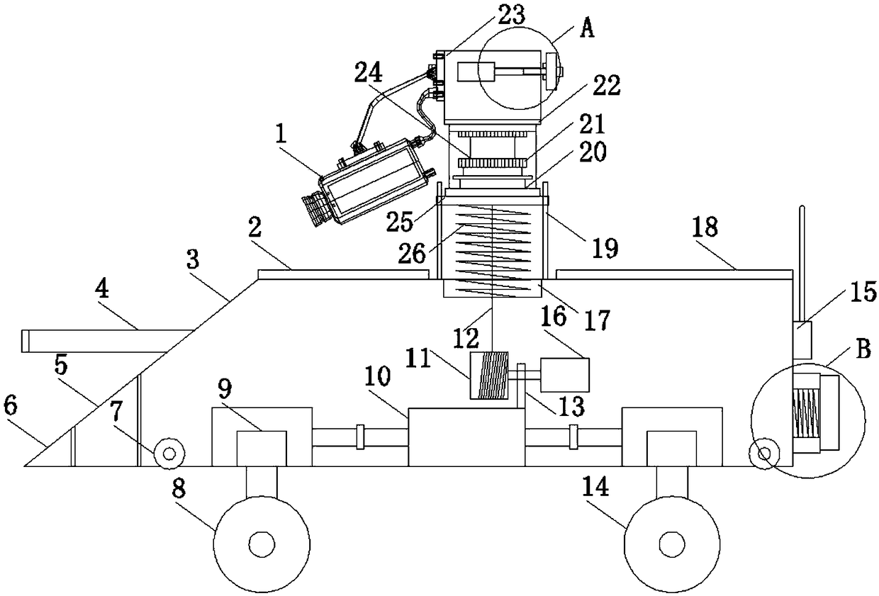
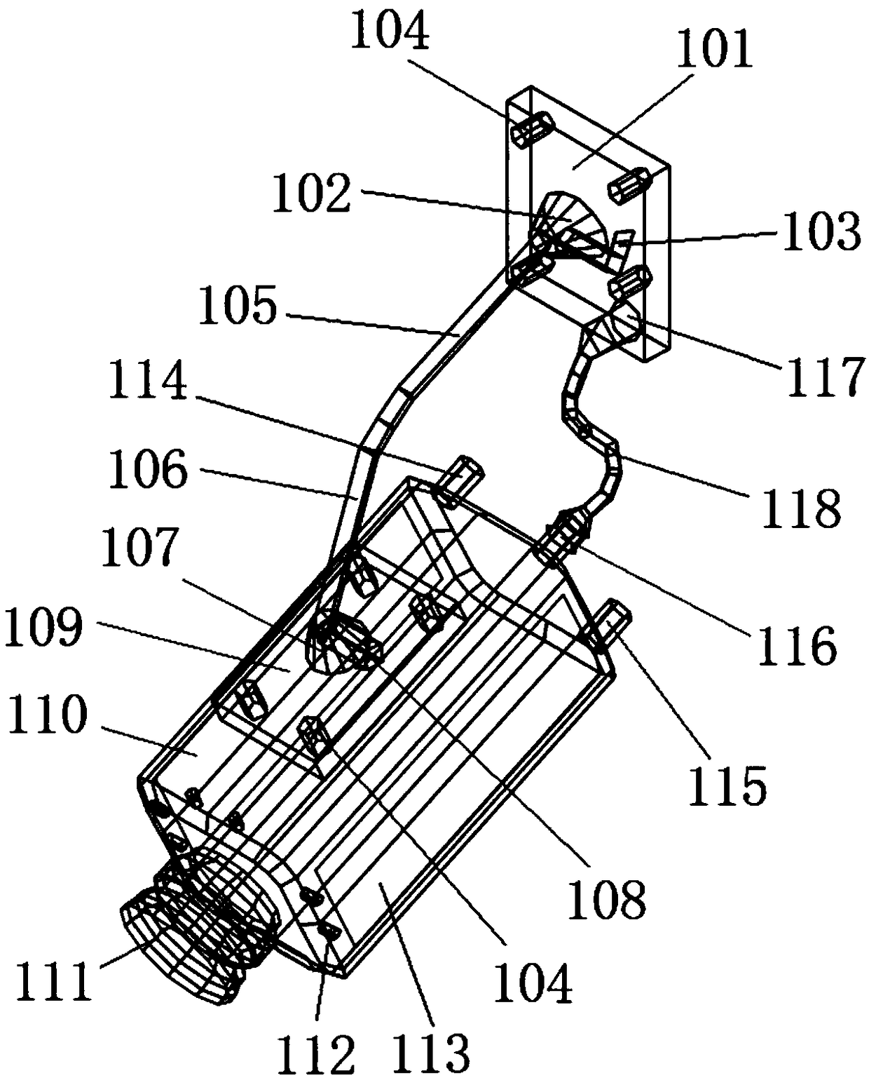
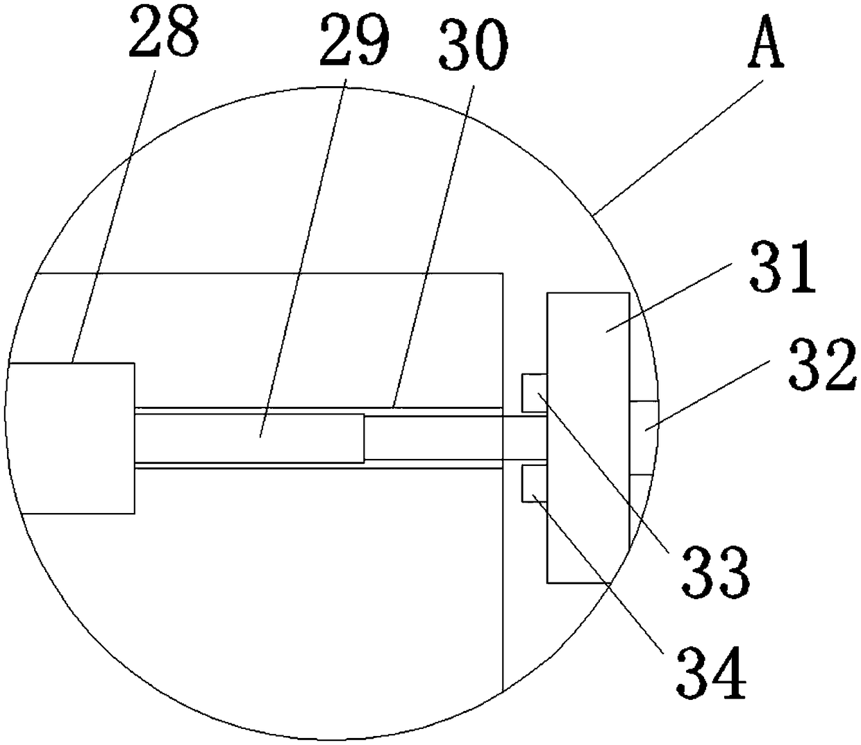
[0036] Such as Figure 1-7 As shown, it shows a specific embodiment of the present invention; as shown in the figure, a substation inspection system disclosed by the present invention includes a mobile trolley 3, a hollow frame 5 is set at the front of the mobile trolley near the bottom end, and the hollowed out The far end of the frame is equipped with a clearing frame 6; the front part of the mobile car is positioned at the top of the hollow frame to set the front buffer frame 4; the bottom of the mobile car is equipped with whe...
PUM
Abstract
The invention discloses a patrol inspection system for a substation, which realizes obstacle clearing and collision avoidance function in the patrol inspection process, and can provide a larger patrolinspection field of view, improve the patrol inspection efficiency and the patrol inspection quality, and reduce the maintenance cost. The system comprises a mobile trolley, a hollow frame is arranged at the position near the bottom end of the front part of the mobile trolley, and a barrier clearing frame is arranged at the far end of the hollow frame;a front buffer frame is arranged above the hollow frame at the front of the mobile trolley; wheels are arranged at the bottom of the mobile trolley; anti-collision component are respectively installed at the rear part and the left and right sideof the mobile trolley; a lifting motor is installed inside the mobile trolley, an output shaft of the lifting motor is provided with a rope winding wheel, and a lifting rope is wound around the ropewinding wheel. The image patrol assembly comprises a base, a first rotating shaft, a first protruding rod, a bolt, a connecting rod, a bending portion, a second rotating shaft, a second protruding rod, a connecting plate, a camera, a lens, a light supplement lamp, a panel lamp, a wireless signal transmitter, a wireless signal receiver, a line outlet, a threading hole, and a hose.
Description
technical field [0001] The invention relates to an inspection system for a substation, in particular to an automatic inspection system for a substation. Background technique [0002] Substation inspection work is an important part of substation operation management. It is an essential basic work to check the operation status of equipment, master the operation rules of equipment, and ensure safe operation. By improving the quality of equipment inspection, the operation and management level of substations can be improved to ensure the safe operation of substation equipment. Traditional manual inspections use paper-based standard inspection workbooks, and inspection personnel manually fill in the inspection results. After the inspection is completed, the inspection record book will be summarized to the power grid center for filing, and necessary maintenance measures will be taken according to the fault records. [0003] With the development of science and technology, there ar...
Claims
Application Information
Patent Timeline
Application Date:The date an application was filed.
Publication Date:The date a patent or application was officially published.
First Publication Date:The earliest publication date of a patent with the same application number.
Issue Date:Publication date of the patent grant document.
PCT Entry Date:The Entry date of PCT National Phase.
Estimated Expiry Date:The statutory expiry date of a patent right according to the Patent Law, and it is the longest term of protection that the patent right can achieve without the termination of the patent right due to other reasons(Term extension factor has been taken into account ).
Invalid Date:Actual expiry date is based on effective date or publication date of legal transaction data of invalid patent.