
A collision-resistant additive manufacturing deposition head

An additive manufacturing and anti-collision technology, applied in the field of additive manufacturing, can solve problems such as affecting the deposition process, cumbersome disassembly of components, and jamming, and achieve the effect of avoiding damage and low cost

Active Publication Date: 2022-04-12
DALIAN UNIV OF TECH
View PDF14 Cites 0 Cited by
  • Summary
  • Abstract
  • Description
  • Claims
  • Application Information

AI Technical Summary

Problems solved by technology

However, the magnetic force of the high-strength magnet is enough to affect the flow of metal material powder and thus affect the deposition process, and there is a problem that the magnetic mechanism absorbs iron filings to reduce the magnetic properties and accelerate the corrosion of the device.
In addition to the magnetic anti-collision mechanism, there is also a mechanical structure to achieve anti-collision, such as the anti-collision device described in the Chinese patent "anti-collision laser head" (authorization number CU 205271151 U), the focusing mirror is placed on the upper body, and the upper and lower body There is also a reset device between them, but this device cannot buffer a large impact force, and it is prone to jamming
Another example is the Chinese patent "Laser processing equipment and its laser head anti-collision assembly" (authorization number CN105382428 A). The arc-shaped mounting seat effectively avoids mechanical jamming and improves the reliability of the assembly. However, it is not easy to disassemble and cannot be Quick replacement of damaged components
[0005] To sum up, the existing additive manufacturing deposition head is easy to damage the internal parts after a rigid collision, and the damaged parts are cumbersome to disassemble and the cost of returning to the factory is high.

Method used


Image

  • A collision-resistant additive manufacturing deposition head
  • A collision-resistant additive manufacturing deposition head
  • A collision-resistant additive manufacturing deposition head

Examples


Embodiment 1

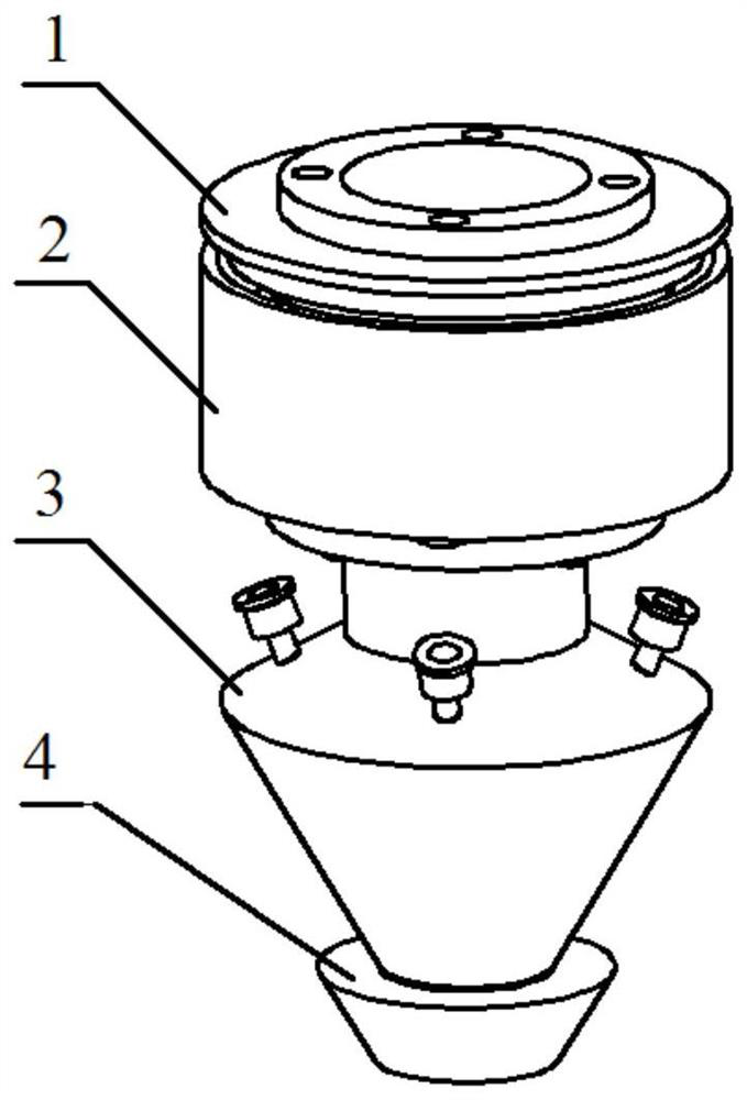
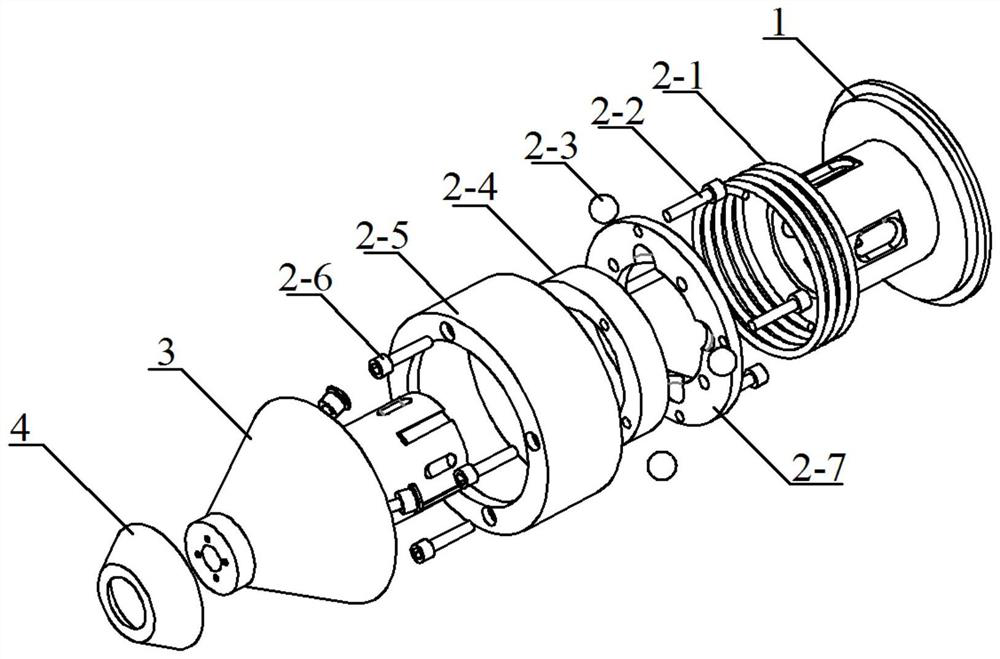
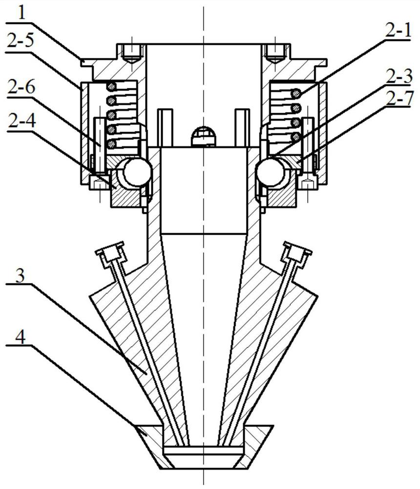
[0037] The present invention is explained in detail by taking laser additive manufacturing with coaxial light powder as an example. Such as figure 2 and image 3 As shown, the upper end of the deposition base 1 is connected with the upper end (without the powder feeding part) of other common laser deposition heads by bolts to ensure that the laser beam can pass through the deposition base.

[0038] The outer diameter of the lower half of the deposition base 1 is 32 mm, and the inner diameter is 28 mm. 4 steps and through grooves are evenly distributed around the lower end, the through grooves are opened on the steps, and the width of the through grooves is 8mm, which allows the rigid balls 2-3 with a diameter of 10mm to only extend into a part of the through grooves.

[0039]The inner diameter of the rigid ball holder 2-7 is the same as the outer diameter of the lower end of the deposition base 1, and the circumference of the inner diameter is provided with four circular gr...

Embodiment 2

[0046] The present invention is explained in detail by taking the TIG arc additive manufacturing of side wire feeding and side blowing shielding gas as an example. Such as Figure 5 , Figure 6 As shown, the upper end of the deposition base 1 is connected to the upper end of other common arc deposition heads by bolts, so as to ensure that the tungsten needle 7 can pass through the deposition base 1 .

[0047] The outer diameter of the lower half of the deposition base 1 is 34 mm, and the inner diameter is 30 mm. There are 3 steps and slots uniformly distributed around the lower end, the slots are opened on the steps, and the width of the slots is 10mm, which allows the rigid balls 2-3 with a diameter of 12mm to only extend into a part of the slots.

[0048] The inner diameter of the rigid ball holder 2-7 is the same as the outer diameter of the lower end of the deposition base 1, and the circumference of the inner diameter is provided with 3 circular grooves that can hold th...


PUM


Abstract

The invention discloses an anti-collision additive manufacturing deposition head, which includes a deposition base and a deposition nozzle, and also includes a buffer impact device and an anti-collision quick change device; the impact force is buffered between the deposition base and the deposition nozzle The device is connected, and the end of the deposition nozzle is connected with the inner wall of the anti-collision quick change device. The invention can buffer longitudinal and transverse collision impact forces when the device collides, thereby protecting the internal structure of the deposition head, and can realize rapid replacement of the deposition nozzle and the low-cost anti-collision quick-change device.

Description

technical field [0001] The invention belongs to the field of additive manufacturing and relates to an anti-collision additive manufacturing deposition head. Background technique [0002] Additive manufacturing technology is a technology based on the principle of discrete accumulation, using powder or wire as processing raw materials, and realizing rapid prototyping through "bottom-up" material accumulation. The advantage of additive manufacturing technology is that it can solve the manufacturing problems of high-performance, complex structure or difficult-to-machine material parts, reduce processing procedures, shorten time costs, and improve raw material utilization. At present, additive manufacturing technology has important applications in the automotive, medical, electronics, aviation and construction industries. [0003] The additive manufacturing system is generally composed of additive deposition heat source, additive feeding device, additive deposition head, protect...

Claims


Application Information

Patent Timeline
Patent Type & Authority Patents(China)
IPC IPC(8): B22F12/53B22F12/41B33Y30/00
CPCB33Y30/00
Inventor 吴东江蔡昕彤朱玟旭牛方勇马广义
Owner DALIAN UNIV OF TECH
Learn More