Flat plate heat pipe and manufacturing method thereof

A technology for flat heat pipes and manufacturing methods, applied in the field of heat pipes, can solve the problems of poor heat transfer performance of flat heat pipes and inability to meet different requirements at the same time, and achieve the effect of avoiding dry burning and ensuring working performance

Inactive Publication Date: 2014-06-18
FURUI PRECISE COMPONENT (KUNSHAN) CO LTD +1
View PDF4 Cites 8 Cited by
  • Summary
  • Abstract
  • Description
  • Claims
  • Application Information

AI Technical Summary

Problems solved by technology

However, since the shape and thickness of the first capillary structure and the second capillary structure are the same, the capillary force is the same everywhere, which cannot meet the different requirements of the heat pipe for the performance of the first capillary structure and the second capillary structure at the same time, resulting in The heat transfer performance of the flat heat pipe is not good

Method used


Image

  • Flat plate heat pipe and manufacturing method thereof
  • Flat plate heat pipe and manufacturing method thereof
  • Flat plate heat pipe and manufacturing method thereof

Examples


Embodiment Construction

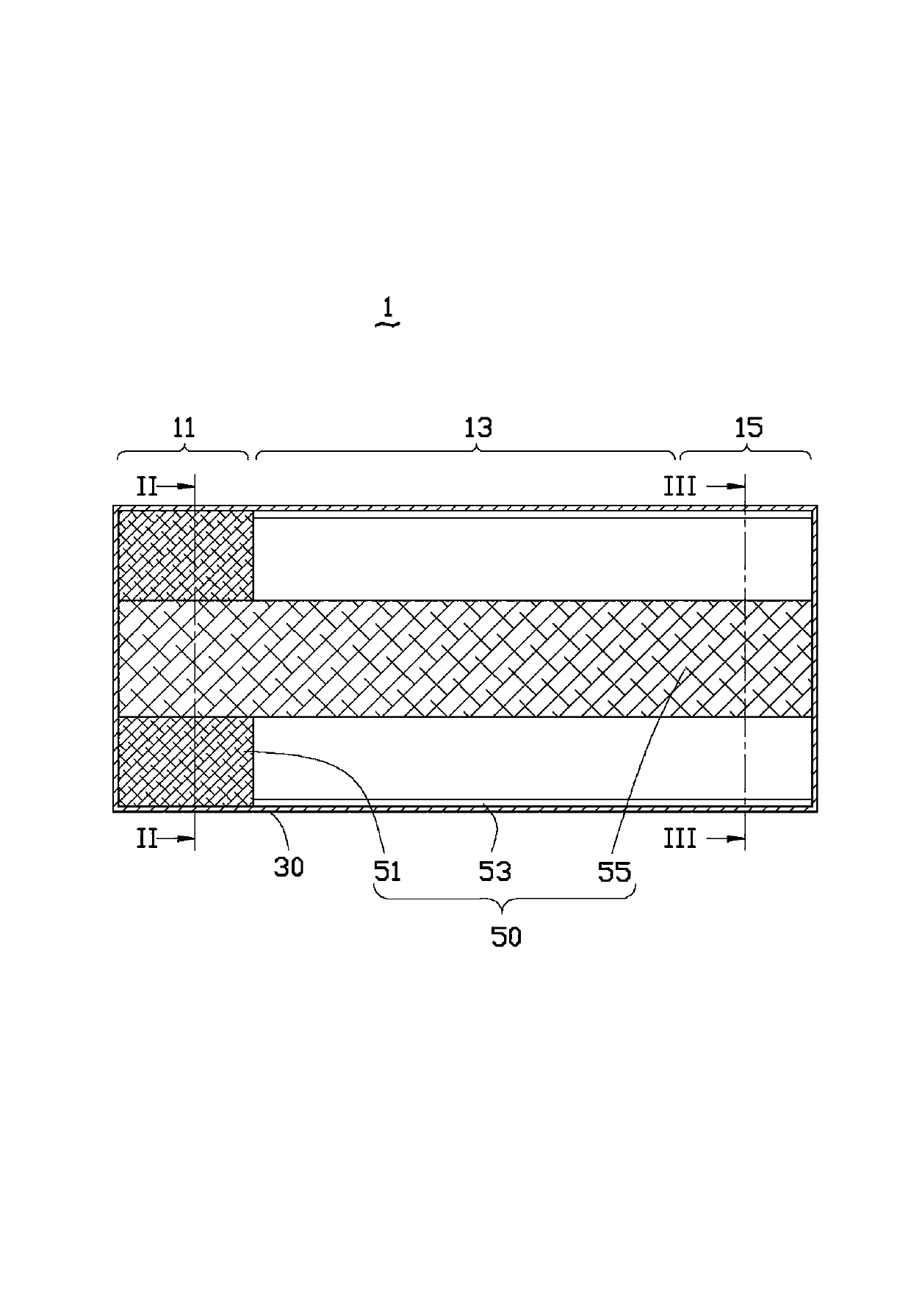
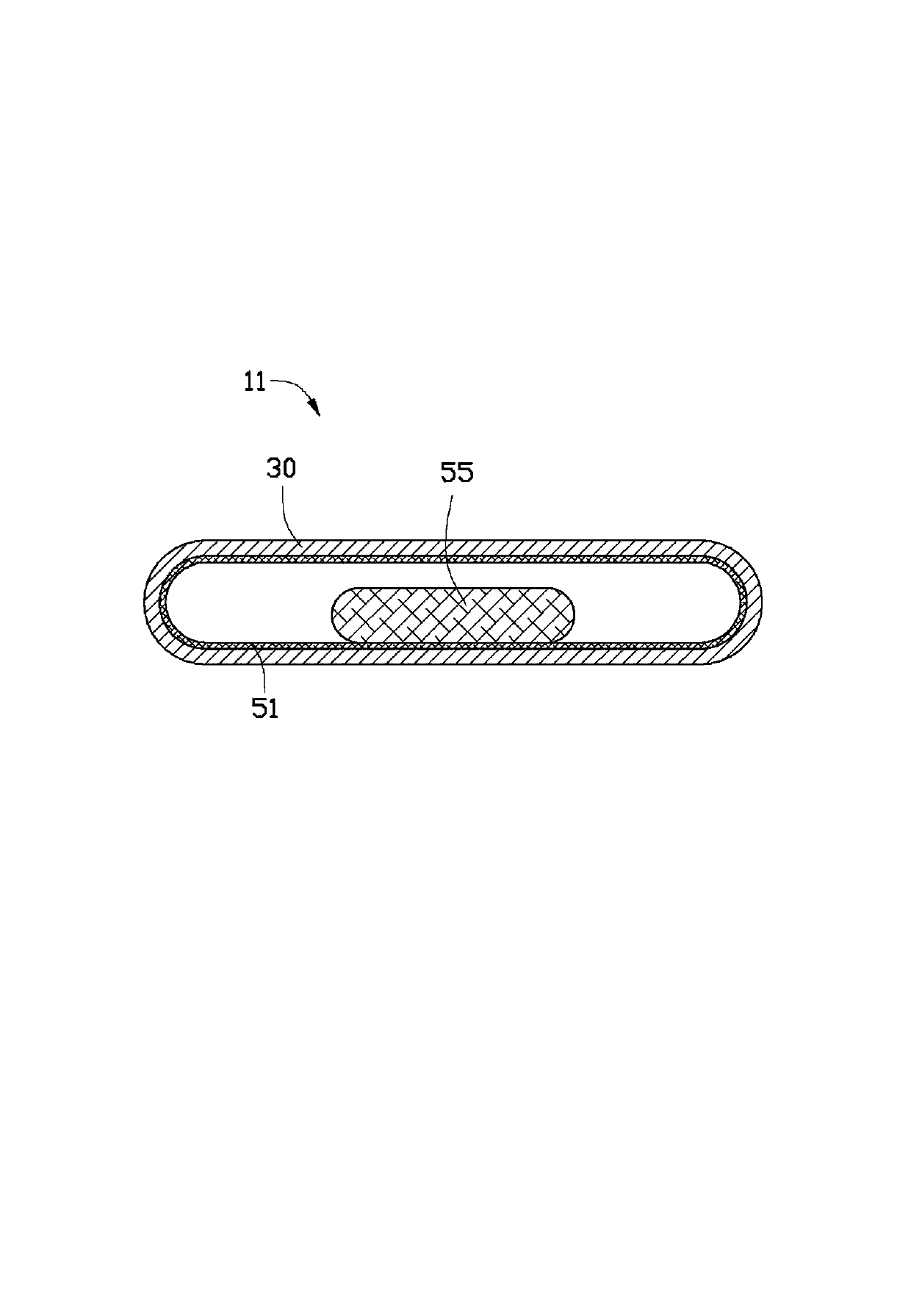
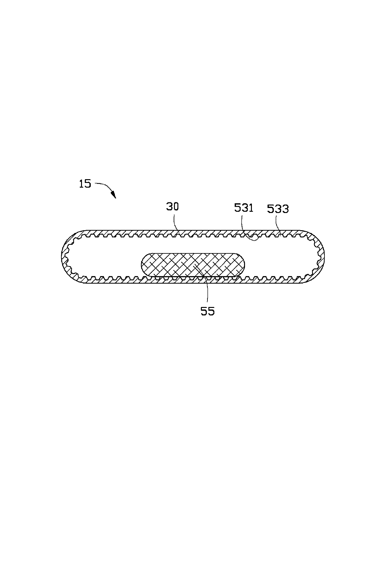
[0022] Such as Figure 1 to Figure 3 Shown is the flat heat pipe 1 of the first embodiment of the present invention. The flat heat pipe 1 is a longitudinal pipe body, along its length direction, there are sequentially connected an evaporation section 11 , a heat transfer section 13 and a condensation section 15 . The flat heat pipe 1 includes a shell 30 , a capillary structure 50 attached to the inner surface of the shell 30 , and a working fluid (not shown) contained in the capillary structure 50 . The housing 30 is a hollow and elongated flat tube with the same depth everywhere and sealed against both ends. The cross section of the housing 30 is racetrack-shaped.

[0023] The capillary structure 50 includes a first capillary structure 51 located at the evaporation section 11, a second capillary structure 53 connected to the first capillary structure 51 and extending from the heat transfer section 13 to the condensation section 15, and a second capillary structure 53 connec...


PUM


Abstract

A flat plate heat pipe is provided with an evaporation section, a heat transfer section and a condensation section which are connected in sequence. The flat plate heat pipe comprises a casing and a capillary structure adhering to the casing. The capillary structure comprises a first capillary structure located on the evaporation section, a second capillary structure and a third capillary structure, wherein the second capillary structure is connected with the first capillary structure and extending from the heat transfer section to the condensation section; and the third capillary structure is connected with the first capillary structure and the second capillary structure and penetrates the evaporation section, the heat transfer section and the condensation section. Capillary force of the first capillary structure is larger than that of the third capillary structure. When the flat plate heat pipe is in use, due to the fact that the capillary force of the first capillary structure is larger than that of the third capillary structure, working fluid accommodated in the third capillary structure can rapidly flow back to the first capillary structure from the third capillary structure under the traction of the capillary force so as to avoid dry burning of the first capillary structure, and working performance of the flat plate heat pipe is guaranteed. The invention further relates to a method for preparation of the flat plate heat pipe.

Description

technical field [0001] The invention relates to a heat pipe, in particular to a flat heat pipe. Background technique [0002] The working principle of the flat heat pipe is the same as that of the traditional heat pipe. Because it has a larger heat conduction area than the traditional heat pipe, and meets the high practical value of "light, thin, short, and small", it is widely used in electronics with a large heat dissipation surface. on the product. [0003] A traditional flat heat pipe includes a metal shell and a continuous capillary structure attached to the inner surface of the metal shell. The capillary structure encloses a steam channel inside it. The flat heat pipe can be sequentially divided into an evaporating section in contact with the heat source and a condensing section extending from the evaporating section along its length direction. The capillary structure includes a first capillary structure located at the evaporation section and a second capillary stru...

Claims


Application Information

Patent Timeline
Patent Type & Authority Applications(China)
IPC IPC(8): F28D15/04
CPCF28D15/046B21D53/02F28D15/0233Y10T29/49353
Inventor 代升亮吴佳鸿
Owner FURUI PRECISE COMPONENT (KUNSHAN) CO LTD
Why Eureka
Try Eureka