A kind of double mixing time difference measurement method and measurement system

A technology of double mixing time difference and measurement method, which is applied in the direction of frequency measurement device, heterodyne/beat frequency comparison, etc., can solve problems such as period ambiguity, and achieve the effect of time difference alignment and accurate time difference measurement

Active Publication Date: 2016-04-20
石家庄数英仪器有限公司
View PDF4 Cites 1 Cited by
  • Summary
  • Abstract
  • Description
  • Claims
  • Application Information

AI Technical Summary

Problems solved by technology

[0005] One of the purposes of the present invention is to provide a double-mixing time difference measurement method to solve the problem of periodic ambiguity in the double-mixing time difference measurement process

Method used


Image

  • A kind of double mixing time difference measurement method and measurement system
  • A kind of double mixing time difference measurement method and measurement system
  • A kind of double mixing time difference measurement method and measurement system

Examples


Embodiment 1

[0053] Embodiment 1, a double mixing time difference measurement system.

[0054] The double-mixing time difference measurement system provided by the invention includes a counting unit, a latch unit, a single-chip computer and a memory. The counting unit is connected to the latch unit, the latch unit is connected to the single-chip microcomputer, and the single-chip microcomputer is connected to the memory.

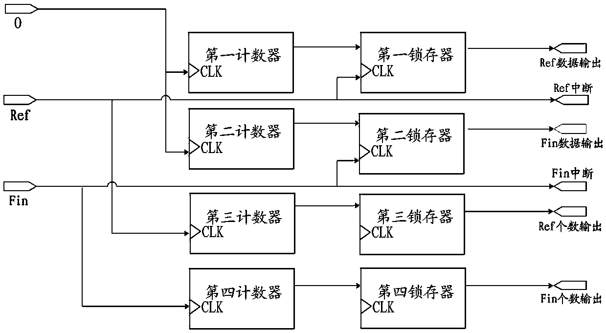
[0055] Such as figure 2 As shown, the figure shows the structural block diagram of the counting unit and the latch unit. The counting unit includes a first counter, a second counter, a third counter and a fourth counter; the latch unit includes a first latch, a second latch, a third latch and a fourth latch. The first counter is connected to the first latch, the second counter is connected to the second latch, the third counter is connected to the third latch, and the fourth counter is connected to the fourth latch.

[0056] The first counter and the second counter a...

Embodiment 2

[0067] Embodiment 2, a double mixing time difference measurement method.

[0068] Such as Figure 4 As shown, the double mixing time difference measurement method provided by the present invention comprises the following steps:

[0069] ① Initialize the parameters and select an uninterrupted public source signal as the reference signal for duration measurement.

[0070] ②Use the first counter and the second counter to respectively obtain the frequency count of the common source signal in real time and convert it into time count.

[0071] ③ To judge whether the rising edge of the reference signal and the signal under test arrives, two interrupt sources can be used to obtain the rising edge of the reference signal and the signal under test to generate an interrupt, and then judge whether the rising edge is interrupted by judging whether the reference signal and the signal under test Arrival; if neither the reference signal nor the measured signal’s rising edge arrives, proceed...


PUM


Abstract

The invention provides a DMTD measuring method and measuring system. According to the DMTD measuring method and measuring system, an uninterrupted common source signal is selected, two counters are used for acquiring the time counting values of the common source signal respectively in real time, when the rising edges of reference signals and the rising edges of detected signals come respectively, the time counting values of the current two counters are acquired respectively, the number of the rising edges of the reference signals and the number of the rising edges of the detected signals align at each other, the two time counting values corresponding to the aligning numbers are subtracted to obtain an accurate time difference value, and other frequency differences, phase differences, Allan variances and the like can be calculated according to the accurate time difference value. The common source signal mode is used, the problem that a traditional exclusive-OR gate mode can not conduct accurate measurement in times of edge overlapping or when two edge time differences are smaller than hardware response time is solved, and the cycle fuzzy phenomenon which commonly exists in the DMTD measuring process is avoided. In brief, the DMTD measuring method and measuring system can achieve quick, accurate, real-time and unlimited measuring with low cost.

Description

technical field [0001] The invention relates to a double-mixing time-difference method, in particular to a double-mixing time-difference measurement method and a measurement system. Background technique [0002] The double-mixing time-difference method is a method for measuring high-stability atomic clocks proposed by D.W.Allan in the 1970s. Today, it has become the most accurate method for single-frequency measurement. It is adopted by many advanced time-frequency laboratories in the world. This method performs time-scaled measurements. [0003] Periodic ambiguity often exists in the process of double-mixing time difference measurement. The period ambiguity phenomenon means that when the double-mixing time-of-flight system is compared, due to the frequency deviation between the reference signal and the measured signal, with long-term measurement, the reference signal and the measured signal will overlap or cycle jump, which will lead to measurement inaccurate phenomenon. ...

Claims


Application Information

Patent Timeline
Patent Type & Authority Patents(China)
IPC IPC(8): G01R23/14
Inventor 邓志成苏志强杜向伟冯卫
Owner 石家庄数英仪器有限公司
Why Eureka
Try Eureka