
Rapid finite element modeling method

A modeling method and finite element technology, applied in special data processing applications, instruments, electrical and digital data processing, etc., can solve the problems of delaying the progress of structural analysis and the process of structural design, and the workload is large, so as to shorten the design cycle. Effect

Inactive Publication Date: 2014-06-18
SHANGHAI AEROSPACE SYST ENG INST
View PDF1 Cites 10 Cited by
  • Summary
  • Abstract
  • Description
  • Claims
  • Application Information

AI Technical Summary

Problems solved by technology

[0005] The above-mentioned conventional modeling methods need to set the material and section properties of each component of the large structure one by one. This step is a huge workload, which seriously delays the progress of structural analysis and structural design.

Method used


Image

  • Rapid finite element modeling method
  • Rapid finite element modeling method

Examples


Embodiment Construction

[0021] The technical solutions in the embodiments of the present invention will be clearly and completely described and discussed below in conjunction with the accompanying drawings of the present invention. Obviously, what is described here is only a part of the examples of the present invention, not all examples. Based on the present invention All other embodiments obtained by persons of ordinary skill in the art without creative efforts fall within the protection scope of the present invention.

[0022] In order to facilitate the understanding of the embodiments of the present invention, specific embodiments will be taken as examples for further explanation below in conjunction with the accompanying drawings, and each embodiment does not constitute a limitation to the embodiments of the present invention.

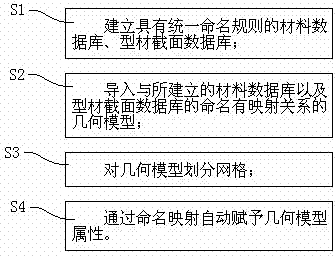
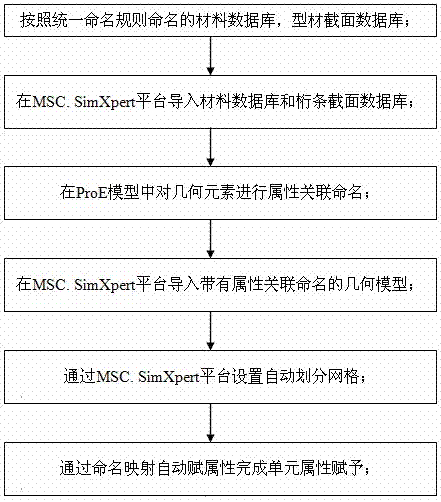
[0023] Such as figure 1 As shown, the present invention mainly comprises four steps: S1, establishes the material database with unified naming rule, stores material data...


PUM


Abstract

The invention discloses a rapid finite element modeling method. The method comprises the following steps: S1, establishing a material database with a uniform naming rule, storing material data, establishing a profile section database with a uniform naming rule, and storing profile section data; S2, importing a geometrical model having a mapping relation with naming of the established material database and the profile section database; S3, partitioning the geometrical model into grids; S4, finding out material data and profile section data which correspond to the geometrical model according to the naming rules, and automatically endowing geometrical model attributes through naming mapping. By adopting the method, preprocessing of a finite element model can be performed effectively and reliably, structures with uniform constructions can be subjected to template processing, and the design periods of structural products are shortened greatly.

Description

technical field [0001] The invention relates to the technical field of modeling, in particular to a fast modeling method for finite elements. [0002] Background technique [0003] In the field of finite element analysis technology, pre-processing modeling takes up more than 60% of the entire analysis time. Conventional modeling techniques allow analysts to establish geometry according to structural design drawings, set materials and section properties one by one, and set boundary conditions to obtain finite elements. Model or directly import the 3D structural model, perform geometric cleaning and various simplifications, set the material and section properties one by one, and set the boundary conditions to obtain the finite element model. [0004] Moreover, the design of large-scale structures, especially those related to spacecraft (such as riveted cabins, fuel storage tanks, composite cabins, etc.) often have complex structures and many parts. With the increase of aeros...

Claims


Application Information

Patent Timeline
Patent Type & Authority Applications(China)
IPC IPC(8): G06F17/50
Inventor 李昊史立涛韩涵王瑞凤冀宾吕榕新唐杰张修科
Owner SHANGHAI AEROSPACE SYST ENG INST
Learn More