
A pressure switch and electric pressure cooker for precise pressure control

A pressure switch, precise technology, applied in pressure cookers, cooking utensils, household appliances, etc., can solve the problems of inaccurate pressure control of pressure switches, user safety threats, easy to exceed safety pressure, etc., to improve use safety and improve pressure control. Accuracy and good product applicability

Active Publication Date: 2016-06-08
JOYOUNG CO LTD
View PDF5 Cites 0 Cited by
  • Summary
  • Abstract
  • Description
  • Claims
  • Application Information

AI Technical Summary

Problems solved by technology

[0004] In the process of using the above-mentioned pressure switch, the inventor found that since the insulating column is located at the fixed connection point, the copper column on the positioning block is located on the side of the insulating column away from the connecting rod, resulting in the existing pressure switch being installed on the outer pot. The error pressure in the cooking cavity corresponding to every error of 1mm will be very large, resulting in inaccurate pressure control by the pressure switch, which may cause excessive pressure in the cooking cavity of the electric pressure cooker. The heating plate does not stop heating, and it is easy to exceed the safe pressure. Threats to user security

Method used


Image

  • A pressure switch and electric pressure cooker for precise pressure control
  • A pressure switch and electric pressure cooker for precise pressure control
  • A pressure switch and electric pressure cooker for precise pressure control

Examples


no. 1 example

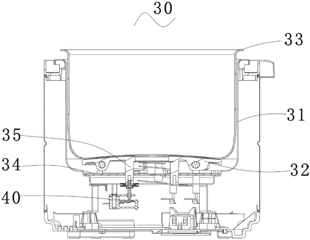
[0059] The invention provides an electric pressure cooker, please refer to image 3 The electric pressure cooker includes a pot cover and a pot body 30, and the pot body 30 includes an outer pot 31, and a heating device is installed on the bottom of the outer pot 31. In this embodiment, the heating device is a heating plate 32. In other embodiments of the present invention Among them, the heating device can also be other conventional heating devices, the heating plate 32 is provided with an inner container 33, the inner container 33 and the pot cover form a cooking cavity, and the heating plate 32 is provided under the legs. Elastic support structure 34, the legs of the heating plate 32 are supported on the elastic support structure 34. In this embodiment, the elastic support structure 34 is located between the bottom of the outer pot 31 and the legs of the heating plate 32, such as the elastic support The structure 34 can be a known structure such as a disc spring, an elastic...

no. 2 example

[0075] Figure 9 is a sectional view of the pressure switch according to the second embodiment of the present invention, Figure 9 structure with Figure 4 The structures are similar, so the same component symbols represent the same components. The main difference between this embodiment and the first embodiment is that the push rod is movable.

[0076] See Figure 9 , in this embodiment, the upper positioning block 45 is made of rigid material, that is, the upper positioning block 45 is a rigid positioning block, and the push rod 56 is installed on the upper positioning block 45 and can move toward the positioning piece 421. And the push rod 56 pushes the positioning piece 421 to disconnect the moving elastic piece 422 from the lower electrode piece 43, specifically, the push rod 56 pushes the positioning piece 4212 to make the moving elastic piece 422 disconnect from the lower electrode piece 43. disconnected, the push rod 56 is located between the connecting rod 41 and t...

no. 3 example

[0083] Figure 10 is a sectional view of the pressure switch according to the third embodiment of the present invention, Figure 10 structure with Figure 9 The structures are similar, so the same component symbols represent the same components. The main difference between this embodiment and the second embodiment is that the pressure switch cannot be reset after it is disconnected.

[0084] See Figure 10 , the upper positioning block 45 is made of rigid material, and a push rod 66 is installed on the upper positioning block 45, and the push rod 66 can move on the upper positioning block 45, and the push rod 66 pushes the positioning shrapnel 4212 to make The moving elastic piece 422 is disconnected from the lower electrode piece 43 , and the push rod 66 is located between the connecting rod 41 and the fixed connection point 47 , specifically, the pushing rod 66 is located above the positioning elastic piece 4212 .

[0085] In this embodiment, the upper positioning block 4...


PUM


Abstract

The invention discloses a pressure switch capable of accurately controlling pressure, and an electric pressure cooker. The pressure switch comprises a connecting rod, wherein an upper positioning block, an upper electrode plate and a lower electrode plate are installed on the connecting rod in sequence, the upper positioning block, the upper electrode plate and the lower electrode plate are insulated from one another, the upper electrode plate comprises a movable clip and a positioning piece, one end of the positioning piece is installed on the connecting rod, the other end of the positioning piece is fixedly connected with the movable clip to enable a fixed connection point to be formed, and the movable clip is in electrical contact with the lower electrode plate. The pressure switch is characterized in that a push rod is installed on the upper positioning block, the push rod pushes the positioning piece to make the movable clip disconnected with the lower electrode plate, and the push rod is located between the connecting rod and the fixed connection point. The pressure switch has the advantages that pressure is controlled accurately, and the applicability is high.

Description

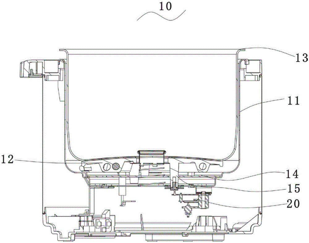
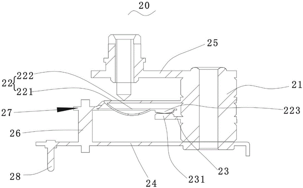
technical field [0001] The invention relates to the field of kitchen cooking utensils, in particular to a pressure switch and an electric pressure cooker for precise pressure control. Background technique [0002] electric pressure cooker, see figure 1 , generally includes a pot cover and a pot body 10, the pot body 10 includes an outer pot 11, a heating plate 12 is installed on the bottom of the outer pot 11, and an inner container 13 is arranged on the heating plate 12, and the inner container 13 and the pot cover form a cooking cavity. In order to prevent the pressure in the cooking cavity from being too high, the existing electric pressure cooker is generally provided with an elastic support structure 14 between the bottom of the outer pot 11 and the feet of the heating plate 12. A pressure switch 20 is provided to control the heating of the heating plate 12. The bottom of the heating plate 12 is fixed with a displacement transmission member 15. As the pressure in the c...

Claims


Application Information

Patent Timeline
Patent Type & Authority Patents(China)
IPC IPC(8): A47J27/08A47J27/09A47J36/00
Inventor 朱泽春于凌振
Owner JOYOUNG CO LTD
Learn More