Four-roller Synchronous Deformation Mechanism of Section Steel Cold Bending Machine

A technology of deformation mechanism and cold bending machine, which is applied in the field of metal profile cold bending machine, which can solve the problems of large friction force on both sides, uncontrollable wire drawing, and displacement of roller printing line, etc., and achieves enlarged adjustment range, flat bottom plate, and straight line The effect of face length

Active Publication Date: 2016-05-11
江苏亚龙汽车有限公司
View PDF6 Cites 0 Cited by
  • Summary
  • Abstract
  • Description
  • Claims
  • Application Information

AI Technical Summary

Problems solved by technology

[0003] In the prior art, the medium-shaped steel cold bending machine is gradually deformed one by one through the transmission of the lower roller. Because the rolled-out steel is driven by a single roller, the speed ratio will be poor, and the friction on both sides is large. The product cannot be controlled in the pass. Scratches and strains on the fish scales on the edge, displacement of the roll printing line, and short straight lines

Method used


Image

  • Four-roller Synchronous Deformation Mechanism of Section Steel Cold Bending Machine
  • Four-roller Synchronous Deformation Mechanism of Section Steel Cold Bending Machine
  • Four-roller Synchronous Deformation Mechanism of Section Steel Cold Bending Machine

Examples


Embodiment Construction

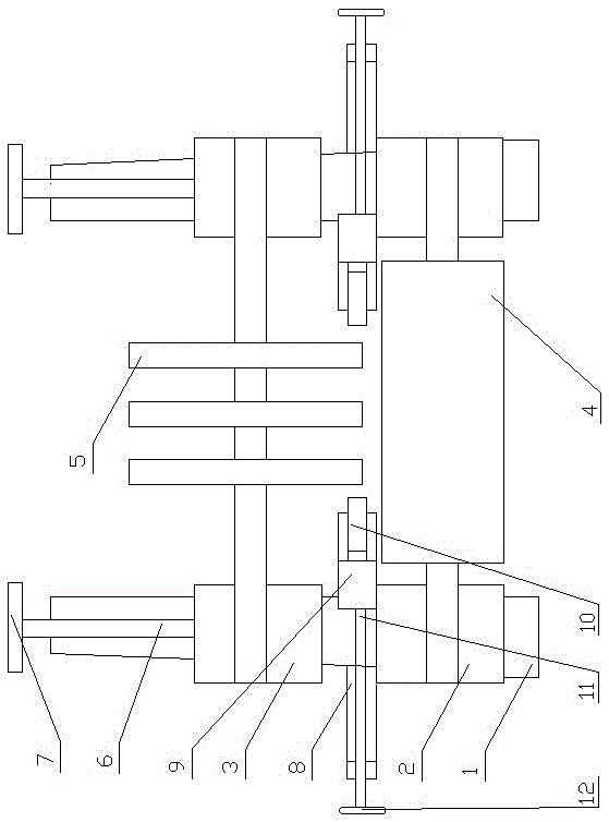
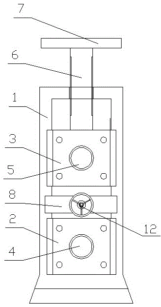
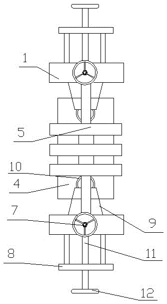
[0011] like figure 1 , 2 , 3, the present invention comprises a frame-shaped support 1 symmetrically arranged left and right, a lower roller support 2 and an upper roller support 3 are respectively symmetrically arranged in the frame-shaped support 1 on both sides, and the lower roller support 3 is fixed on the frame-shaped The lower part of the bracket 1, the upper roller support 2 is installed above the lower roller support 2, the powered lower roller 4 and the unpowered upper roller 5 are installed between the frame-shaped supports 1 on both sides, and the two ends of the powered lower roller 4 are respectively supported On the lower roller support 2 of the frame-shaped support 1 on both sides, the two ends of the unpowered upper roller 5 are respectively supported on the upper roller support 3 of the frame-shaped support 1 on both sides.

[0012] The middle part of the upper end of the upper roller support 3 of the frame-shaped support 1 on both sides is fixedly connected...


PUM


Abstract

The invention discloses a four-roller synchronous deformation mechanism of a profile steel forming mill, and relates to metal proximate matter forming mills. The mechanism comprises frame type supports which are arranged in a bilateral symmetry mode, lower roller supports and upper roller supports are symmetrically arranged in the frame type supports on the two sides respectively, power lower rollers and unpowered upper rollers are arranged between the frame supports on the two sides, the middles of the upper ends of the upper roller supports of the frame type supports on the two sides are respectively and fixedly connected with a first vertical lead screw, the first lead screws penetrate through the frame type supports upwards respectively, side roller frames are symmetrically fixed to the outer sides of the lower roller supports on the two sides, side roller bases are arranged on the lower roller supports on the two sides respectively, side rollers are axially positioned at the inner side ends of the side roller bases, and the middles of the outer side ends of the side roller bases are respectively and fixedly connected with a second horizontal lead screw. Through improvement and innovation, the quality is greatly improved, the base plate of the product is flat, scratching and scale damage cannot happen to the two side portions, stretching is avoided, a roller printing line is not displaced, and the linear face is long.

Description

technical field [0001] The invention relates to a metal profile cold bending machine, in particular to a four-roller synchronous deformation mechanism of a profile steel cold bending machine. Background technique [0002] Compared with hot-rolled products, cold-formed steel has reasonable geometric shape, beautiful appearance and light weight. Any shape that cannot be rolled by hot-rolled products can be designed by cold-rolled section steel through reasonable design. [0003] In the prior art, the medium-shaped steel cold bending machine is gradually deformed one by one through the transmission of the lower roller. Because the rolled-out steel is driven by a single roller, the speed ratio will be poor, and the friction on both sides is large. The product cannot be controlled in the pass. Scratches and strains on the fish scales on the edge, displacement of the roll printing line, and short straight lines. Contents of the invention [0004] The object of the present inve...

Claims


Application Information

Patent Timeline
Patent Type & Authority Patents(China)
IPC IPC(8): B21D7/08
Inventor 丁凤友房发成
Owner 江苏亚龙汽车有限公司
Why Eureka
Try Eureka