Rotary cushion valve, rotary hydraulic system and engineering machine

A rotary buffer and hydraulic system technology, which is applied in the direction of mechanical equipment, fluid pressure actuators, servo motors, etc., can solve the problem that the rotary buffer valve cannot realize the buffer function, etc., and achieve the effect of sufficient oil replenishment and rotary buffering

Active Publication Date: 2014-06-25
SANY AUTOMOBILE HOISTING MACHINERY
View PDF7 Cites 19 Cited by
  • Summary
  • Abstract
  • Description
  • Claims
  • Application Information

AI Technical Summary

Problems solved by technology

[0003] In view of this, the present invention aims to propose a rotary buffer valve, a rotary hydraulic system and construction machinery to solve the problem that the rotary buffer valve cannot realize the buffer function when the rotary motor rotates at idle speed

Method used


Image

  • Rotary cushion valve, rotary hydraulic system and engineering machine

Examples


Embodiment Construction

[0025] It should be noted that, in the case of no conflict, the embodiments of the present invention and the features in the embodiments can be combined with each other. The present invention will be described in detail below with reference to the accompanying drawings and examples.

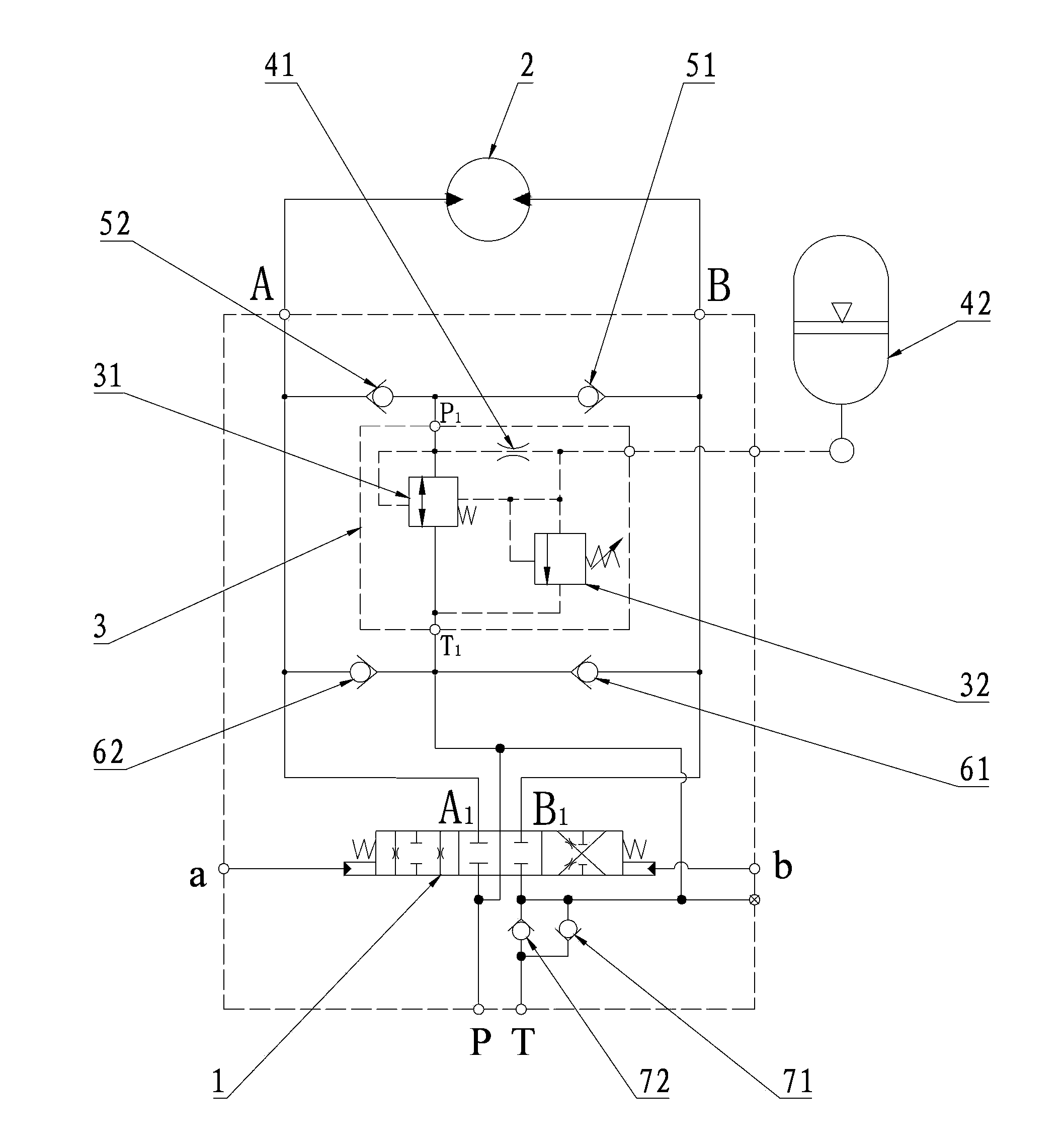
[0026] This embodiment provides a rotary buffer valve, such as figure 1 As shown in the mark 3, the rotary buffer valve is a pilot relief valve 3 with a remote control port, including a main valve 31 and a pilot valve 32, and a damping hole 41 and an elastic container are connected to the remote control port 42. The specific working process and cushioning principle of the rotary buffer valve will be further explained in the rotary hydraulic system described below, and will not be repeated here.

[0027] This embodiment also provides a rotary hydraulic system, the hydraulic system is provided with the above-mentioned rotary buffer valve, figure 1 That is the relevant drawings, as shown in the f...


PUM


Abstract

The invention provides a rotary cushion valve, a rotary hydraulic system and an engineering machine. The rotary cushion valve comprises a pilot overflow valve. The pilot overflow valve comprises a main valve and a pilot valve, a delay decompression device is arranged on a pilot oil passage from the main valve to the pilot valve, and pressure change of a spring cavity can lag under the effect of the delay decompression device. The rotary cushion valve, the rotary hydraulic system and the engineering machine have the advantages that the delay decompression device which comprises components such as a damping hole and an elastic container is arranged on the pilot oil passage of the pilot overflow valve of the rotary cushion valve, a decompression procedure of the main valve of the pilot overflow valve can be delayed under a delay effect of the damping hole or a volume effect of the elastic container, accordingly, the rotary cushion valve can be started when impacted, the problem that an existing overflow valve (at a high setting pressure) cannot be started when impacted at a low pressure in a rotary procedure can be solved, and a rotary cushion effect can be effectively realized.

Description

technical field [0001] The invention relates to the field of construction machinery, in particular to a rotary buffer valve, a rotary hydraulic system and construction machinery. Background technique [0002] Generally speaking, the moment of inertia of the slewing mechanism of construction machinery is relatively large, and it is easy to cause a slewing impact when it stops, which seriously affects the control performance of the slewing action. The rotary shock valve is used to control the hydraulic components of the rotary action. The existing rotary shock valve is generally connected to the A port and the B port of the rotary motor (or the pressure is released to the T port) through the relief valve and the one-way valve to realize the buffer function. Its working principle is that when the pressure of port A and port B of the rotary motor reaches the opening pressure of the relief valve, the relief valve opens to realize the connection between port A and port B of the ro...

Claims


Application Information

Patent Timeline
Patent Type & Authority Applications(China)
IPC IPC(8): F15B13/02F15B11/02
Inventor 刘正雷易迪升侯敏
Owner SANY AUTOMOBILE HOISTING MACHINERY
Why Eureka
Try Eureka