Light guide body and lighting device

A technology for lighting devices and light guides, which is applied in the field of light guides, and can solve the problems of smaller cross-sectional area, decreased light quantity, and reduced light quantity of guided light, etc.

Active Publication Date: 2014-06-25
KOITO MFG CO LTD
View PDF6 Cites 5 Cited by
  • Summary
  • Abstract
  • Description
  • Claims
  • Application Information

AI Technical Summary

Problems solved by technology

Therefore, in a rod-shaped light guide, when it is desired to obtain a linear light-emitting surface that is narrower than the diameter and / or width of the rod, it is necessary to use a shield (mask) or the like to shield the light from the light-emitting surface. Part of the emitted light makes a part of the light exit surface narrower, and the light exit efficiency will decrease
On the other hand, it is conceivable to make the rod diameter and / or width of the rod-shaped light guide smaller so that the light emitting surface becomes narrower. The area will also become smaller, the amount of light guided by the light will decrease, and the amount of light emitted from the light exit surface will also decrease
In this way, it is difficult to make the conventional rod-shaped light guide emit a narrow-width linear light-emitting pattern with high luminosity.

Method used


Image

  • Light guide body and lighting device
  • Light guide body and lighting device
  • Light guide body and lighting device

Examples


Embodiment Construction

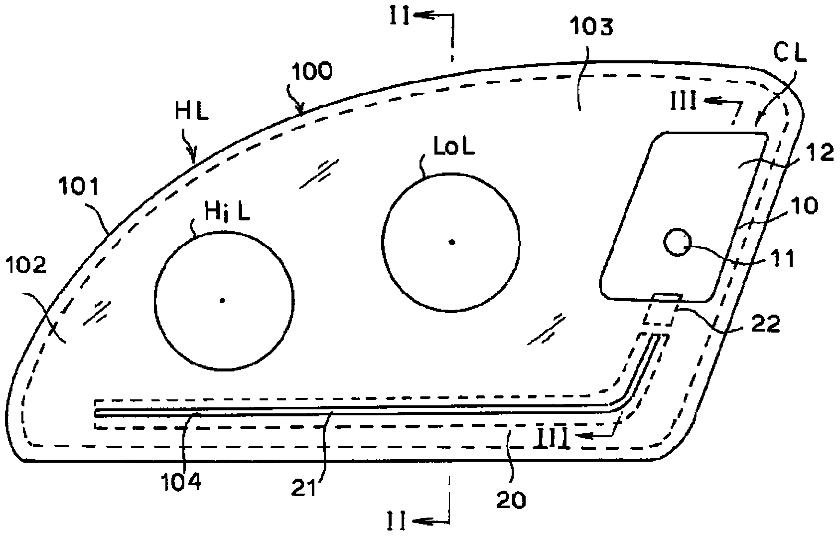
[0017] Next, embodiments of the present invention will be described with reference to the drawings. figure 1 It is a front view of an embodiment in which the illuminating device of the present invention is applied to a position marker integrated with a headlight of an automobile, and the light guide of the present invention is configured as a light emitting body of a part of the position marker. The headlight HL is a left headlight provided on the left front portion of the vehicle, and is configured as a composite headlight including a high beam HiL, a low beam LoL, and position marker lights CL. The headlamp HL includes a lamp housing 100 in which the high beam HiL, low beam LoL, and position marker lamp CL are housed in units, and the lamp housing 100 includes a container with an open front. Shaped lamp body 101 and a translucent front cover 102 mounted on the front opening.

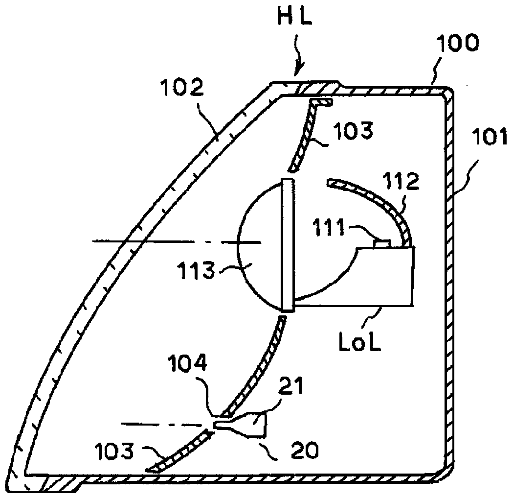
[0018] figure 2 is along figure 1 The vertical cross-sectional view along line II-II of , shows...


PUM


Abstract

The invention provides a light guide body and a lighting device, which comprises a main light guide part (211) and a side light guide part (212). The end face of the main light guide part (211), along the length direction, is served as a light incident part (210) and is in the shape of a light-conducting rod along the length direction. The side light guide part (212) is protruded along one lateral direction of the main light guide part, vertical to the length direction thereof. The top of the protruded direction of the side light guide part (212) is relatively narrow to form a light emitting part (213). The side surface of one side of the main light guide part (211), opposite to the protruded side of the side light guide part (212), is provided with a light reflecting part (214) used for reflecting the light transmitted from the main light guide part (211) towards the top of the side light guide part (212). The cross section of the side light guide part (212), along a direction vertical to the length direction, is cone-shaped. In this way, the light transmitted by the light emitting part (213) is converged, so that the luminosity of the emitted light is improved.

Description

technical field [0001] The present invention relates to a light guide composed of a light-transmitting member, and more particularly to a light guide and an illuminating device having a light emitting portion that emits light having a narrow width in a linear manner. Background technique [0002] The light guide is formed of a light-transmitting member, and is used as a luminous body in which light incident from a part of its surface is transmitted (propagated) inside the light-transmitting member, and is configured so that the transmitted light passes through other parts of the surface of the light-transmitting member. Part of it is emitted to the outside to emit light in a desired pattern. This light guide body is sometimes also used as, for example, a car lamp and / or a lighting device for illuminating a part of the vehicle body. effect is used. Japanese Patent Application Laid-Open No. 2012-4003 proposes a technique in which a substantially L-shaped rod-shaped light gui...

Claims


Application Information

Patent Timeline
Patent Type & Authority Applications(China)
IPC IPC(8): G02B6/00F21V8/00F21S8/10F21W101/02F21Y101/02F21W107/10
CPCF21S48/2237F21S48/2268F21S43/237F21S43/245
Inventor 高桥晴仁风冈成彦
Owner KOITO MFG CO LTD
Why Eureka
Try Eureka