Lighting effect enhancing device of solar cell

A technology of solar cells and solar panels, applied in the directions of circuits, optics, installation, etc., which can solve the problems of high cost, restrictions on popularization and implementation, and inability to make full use of solar light energy, so as to avoid burning and increase output power.

Inactive Publication Date: 2013-02-13
黎昌兴 +1
View PDF3 Cites 2 Cited by
  • Summary
  • Abstract
  • Description
  • Claims
  • Application Information

AI Technical Summary

Problems solved by technology

[0005] In addition, in the prior art, people also set a "pinchfield" annular lens on the top of the solar panel, and the "pinchfield" annular lens can focus the sunlight in order to gather more light to the solar panel. On solar panels, however, there is a risk that solar panel areas may be burned due to excessive light energy concentrated on a certain solar panel area
Also, due to the loss of light energy in the process of passing through the prism, the light energy of solar energy cannot be fully utilized.
In addition, the high cost of the "Pinch Fill" annular lens also restricts the popularization and implementation of this technical solution.

Method used


Image

  • Lighting effect enhancing device of solar cell
  • Lighting effect enhancing device of solar cell
  • Lighting effect enhancing device of solar cell

Examples


Embodiment 1

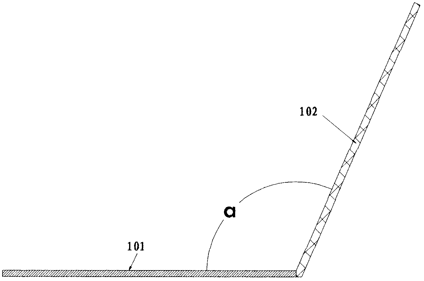
[0037] figure 1 A longitudinal cross-sectional structure and a schematic diagram of a principle of a solar cell light efficiency enhancement device provided in this embodiment.

[0038] see figure 1 As shown, the device for enhancing light efficiency of a solar cell provided in this embodiment mainly includes: a solar cell panel, and a plane reflector. Its connection relationship is as follows:

[0039] The plane reflector is installed on the edge of the solar panel, and the angle α formed between the upper surface of the plane reflector and the upper surface of the solar panel is an obtuse angle, that is, α is greater than 90 degrees but less than 180 degrees.

[0040] The angle α formed between the upper surface of the plane reflector and the upper surface of the solar panel can be calculated and determined according to the current area of ​​the solar panel and the width of the plane reflector, so as to maximize the use of solar cells on the basis of determining the equipm...

Embodiment 2

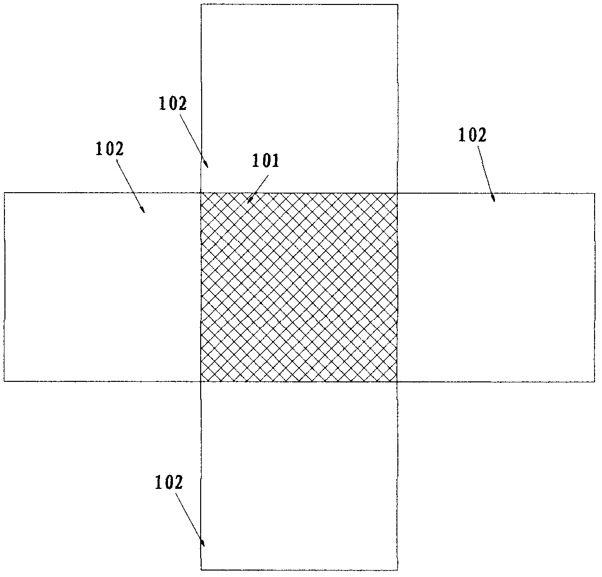
[0054] figure 2 It is a schematic top view structure diagram of the solar cell light efficiency enhancing device provided in this embodiment.

[0055] Referring to Figure 22, the solar cell light efficiency enhancement device can be set into the following structure:

[0056] Specifically, 4 rectangular plane reflectors are arranged around the rectangular solar panel, and the 4 rectangular plane reflectors are respectively installed on the edges around the solar panel. The edges of the battery are the same length.

[0057] In order to make the solar cell light efficiency enhancing device of this embodiment easier to install and to make it more structurally stable during use, a bucket-shaped installation frame can also be set for this embodiment, and the cross-section of the top opening of the installation frame The area is larger than the cross-sectional area of ​​the bottom, the solar cell panel is fixed on the center bottom of the installation frame, and the plane reflecto...

Embodiment 3

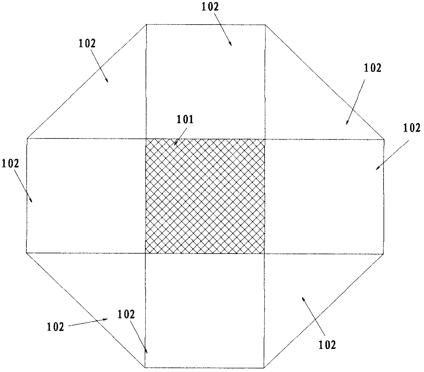
[0060] The inventor found in the test of the present invention that the larger the plane reflector in theory, the more sunlight it catches, and the more electricity the solar panel can produce, but in fact considering the strength, weight, and Thin glass is fragile, so the size, weight and cost of the solar cell light efficiency enhancement device are comprehensively considered and adopted Figure 3-5 The solar cell light efficiency enhancement device with the structure shown has practical significance for the application and popularization of photovoltaic conversion, and can realize photovoltaic conversion into thousands of households.

[0061] image 3 It is a schematic top view structure diagram of a solar cell light efficiency enhancing device provided in this embodiment; Figure 4 Schematic diagram of the vertical cross-sectional structure of the solar cell light efficiency enhancement device provided in this embodiment; Figure 5 It is a schematic diagram of the three-...


PUM


Abstract

The invention provides a lighting effect enhancing device of a solar cell, which comprises a solar cell panel and a plane mirror, wherein the plane mirror is arranged on the edge of the solar cell panel, and an obtuse angle is formed between the upper surface of the plane mirror and the upper surface of the solar cell panel. By applying the scheme, lower cost can be adopted, electric energy output by the solar cell panel is increased, and the lighting effect enhancing device is easily implemented.

Description

technical field [0001] The invention relates to the field of photovoltaic cells, in particular to a solar cell light efficiency enhancing device. Background technique [0002] A solar panel is a device that absorbs sunlight and converts it into electricity. In the prior art, from the perspective of energy conversion, the photovoltaic conversion efficiency of existing solar panels is not high, generally less than 20%. [0003] The power of a solar panel is approximately proportional to the solar light that irradiates the solar panel. In order to obtain more electric energy, the most common method is to increase the area of ​​the solar panel. In practice, the most common method is to increase the solar panel The area of ​​the solar panel, in practical application, many batteries are often combined together to form a large solar panel matrix to form usable electrical energy. However, solar panels have the problem of high cost. [0004] In addition, in the prior art, the sens...

Claims


Application Information

Patent Timeline
Patent Type & Authority Applications(China)
IPC IPC(8): H01L31/052G02B7/182
CPCY02E10/52H01L31/0525H01L31/0547
Inventor 陇涤湘黎昌兴
Owner 黎昌兴
Why Eureka
Try Eureka