Driving Circuit and Driving Method

A driving circuit and driving module technology, applied in the field of lighting systems, can solve problems such as excessive noise concentration

Inactive Publication Date: 2016-08-03
PRINCETON TECHNOLOGY
View PDF2 Cites 0 Cited by
  • Summary
  • Abstract
  • Description
  • Claims
  • Application Information

AI Technical Summary

Problems solved by technology

[0004] Obviously, since n channels are simultaneously turned on at the beginning of each display period DP, the current on the power line Vp suddenly increases from zero to n times the current value of a single channel, which will cause excessive noise to be concentrated on the display Beginning of cycle DP

Method used


Image

  • Driving Circuit and Driving Method
  • Driving Circuit and Driving Method
  • Driving Circuit and Driving Method

Examples


Embodiment Construction

[0019] In order to make the above and other objects, features and advantages of the present invention more comprehensible, preferred embodiments are listed below and described in detail in conjunction with the accompanying drawings.

[0020] The following description is of the best mode for carrying out the invention. Those skilled in the art should be able to understand that some modifications, substitutions and substitutions can be made without departing from the spirit and structure of the present invention. The scope of the present invention should depend on the scope of the appended patent application.

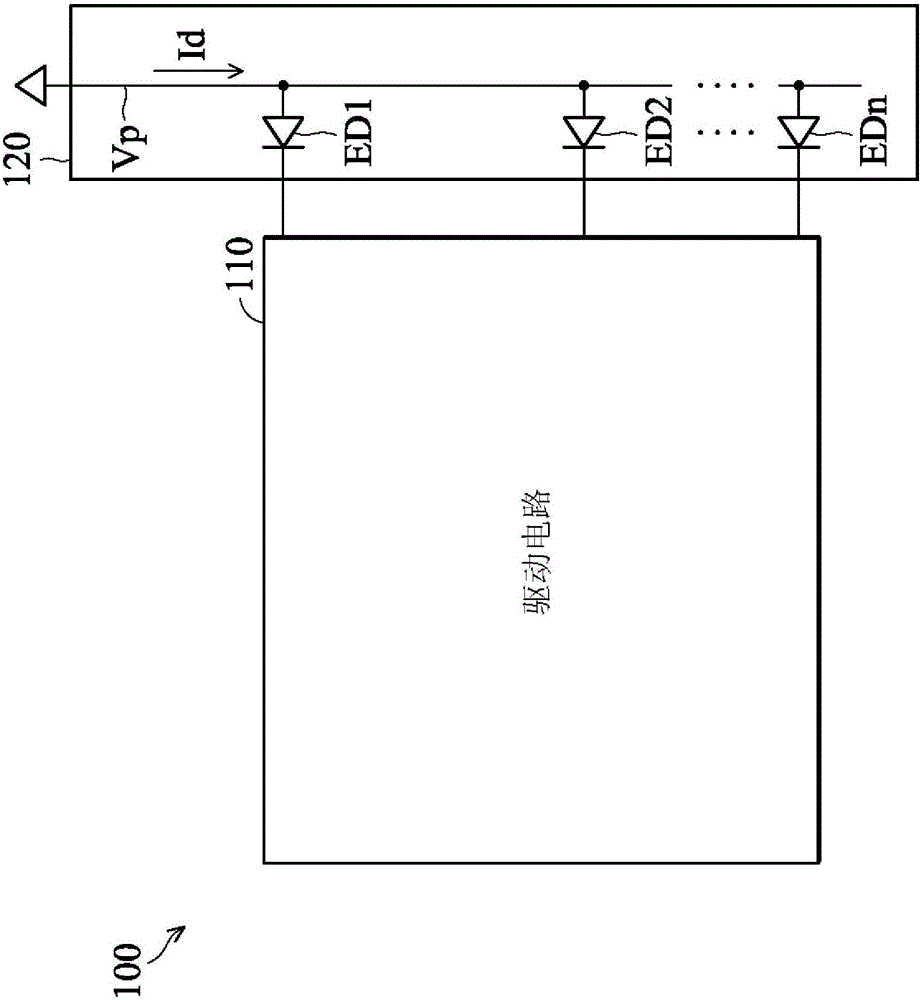
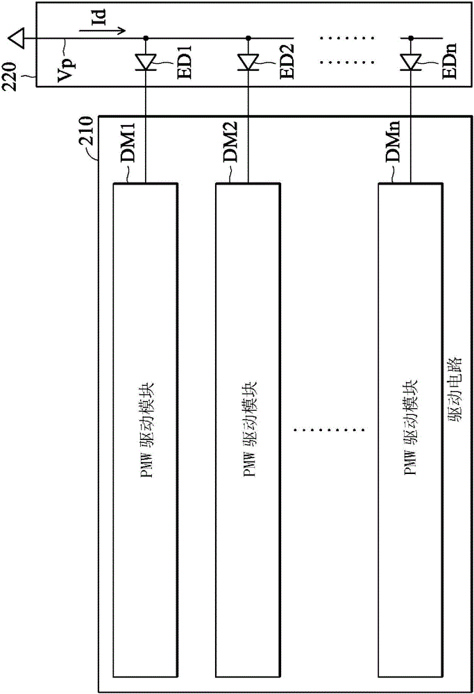
[0021] figure 2 It is a schematic diagram of the driving circuit of the present invention. Such as figure 2 As shown, the driving circuit 210 includes a plurality of PWM driving modules DM1-DMn for respectively driving a plurality of light-emitting units ED1-EDn in the light-emitting module 220, wherein the light-emitting units ED1-EDn are coupled in parallel, and ea...


PUM


Abstract

The invention provides a drive circuit and a drive method. The drive circuit comprises a first PWM drive module and a second PWM drive module. The first PWM drive module generates a first square wave signal according to a first data signal of a data stream, and the first square wave signal is used for driving a first light-emitting unit. The first square wave signal represents the light-emitting time of the first light-emitting unit in a display period. The second PWM drive module generates a second square wave signal according to a second data signal of the data stream, and the second square wave signal is used for driving a second light-emitting unit. The second square wave signal represents the light-emitting time of the second light-emitting unit in the display period. The first square wave signal and the second square wave signal have different phases. By the adoption of the drive circuit and the drive method, the probabilities of generation of currents of all time points in the display period are average, so that an instant load caused on a power line when the light-emitting units are powered on at the same time is reduced.

Description

technical field [0001] The present invention relates to a lighting system, in particular to a driving circuit. Background technique [0002] Figure 1A A schematic diagram of a lighting system. Such as Figure 1A As shown, the lighting system 100 has a driving circuit 110 and a lighting module 120 . The driving circuit 110 has n channels to drive the light-emitting units ED1-EDn, and each light-emitting unit ED1-EDn is connected to the power line Vp. [0003] Figure 1B A graph showing the relationship between current and time on the power supply line. Such as Figure 1B As shown, the line Cv1 represents the current of the first channel, the line Cv2 represents the current of the second channel, the line Cv3 represents the current of the third channel, and the line Cvn represents the current of the nth channel. The line Cvs represents the total current of the lines Cv1 to Cvn, which is also the current on the power line Vp. [0004] Obviously, since n channels are simu...

Claims


Application Information

Patent Timeline
Patent Type & Authority Patents(China)
IPC IPC(8): H05B37/02
CPCY02B20/40
Inventor 苏锦标陈炯宏许建德
Owner PRINCETON TECHNOLOGY
Why Eureka
Try Eureka