A Stamping Automatic Line Turnover Mechanism

A flipping mechanism and automatic line technology, applied in metal processing equipment, feeding devices, manufacturing tools, etc., can solve problems such as high coordination of actions and parts of the mechanism, complicated circuit control, and restrictions on the efficiency of the production line, etc., to achieve structural Streamlined, perfect action, accurate flipping process effect

Inactive Publication Date: 2016-12-28
NINGBO XINYONGCHENG NUMERICAL CONTROL AUTOMATION EQUIP
View PDF1 Cites 1 Cited by
  • Summary
  • Abstract
  • Description
  • Claims
  • Application Information

AI Technical Summary

Problems solved by technology

[0002] At present, the known overturning mechanisms are generally clamped by mechanical fingers, and then overturned. However, when taking and discharging materials in the vertical direction after blanking thin plate stampings, because the clamping part is covered, it must go through a series of operations. The whole process is divided into unloading-support-clamp in place-clamping-return support-turn over-support-clamp release-return clamp-retrieval. These 10 processes require many mechanisms to complete. Action coordination and mechanism parts are highly required, and circuit control is much more complicated, and because of the complexity of these actions, the efficiency of the entire production line is often restricted.
[0003] For example, the application number is ZL201010522707.0, the publication number is CN102452014A, and the application date is 2010.10.20 "A Turning Mechanism" discloses a turning mechanism that can directly place the work in the turning frame and take out the workpiece after the operation is completed. , this invention has a simple mechanism and a simple process, but the invention is still operated manually, which is not convenient for practical application, and the applicable field is very narrow, which is not conducive to large-scale promotion

Method used


Image

  • A Stamping Automatic Line Turnover Mechanism
  • A Stamping Automatic Line Turnover Mechanism

Examples


Embodiment

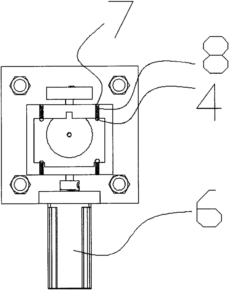
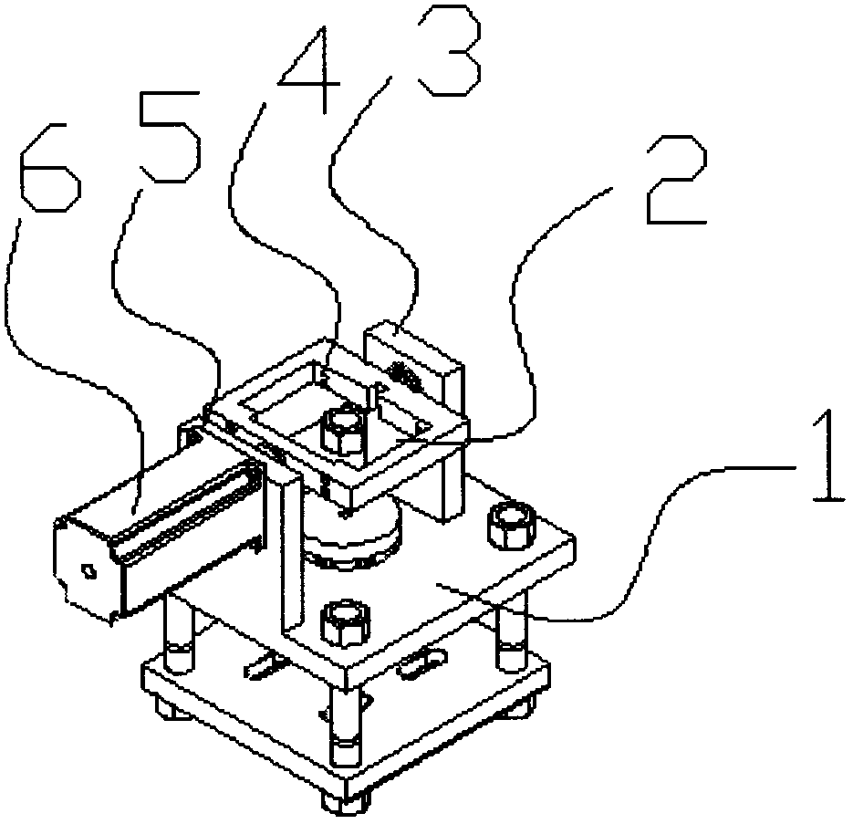
[0017] Such as figure 1 , 2 As shown, a stamping automatic line turning mechanism includes a body 1. A fixed plate 3 and a motor plate 5 are installed on the body 1. A rotating frame 2 is placed between the fixed plate 3 and the motor plate 5. The rotating frame 2 and the fixed plate 3 Through bolt connection, the rotating frame 2 and the motor plate 5 are connected by a motor 6 mounted on the motor plate 5. The motor 6 is connected to the PLC system. The rotating frame 2 is provided with a mold cavity 8 in which a limit mechanism is placed , The limit mechanism includes a spring 7 and a ball 4, the spring 7 is installed in the mold cavity 8, and the ball 4 is installed at the top of the spring 7. There are 4 groups of the limit mechanism, and each group of limit mechanisms includes 2 limit mechanisms, The two limit mechanisms are vertically arranged side by side, and the motor 6 is a stepping motor.

[0018] When the vacuum sucker puts the product into the rotating frame 2, the ...


PUM


Abstract

The invention discloses a turnover mechanism of an automatic stamping line. The turnover mechanism of the automatic stamping line comprises a body; a fixing plate and a motor plate are mounted on the body; a rotating frame is arranged between the fixing plate and the motor plate, connected with the fixing plate through bolts, and connected with the motor plate through a motor mounted on the motor plate; the motor is connected with a PLC (Programmable Logic Controller) system; a mould cavity is arranged in the rotating frame; a limit mechanism is arranged in the mould cavity. The turnover mechanism of the automatic stamping line can greatly reduce the operating processes and improve production efficiency, is simple and compact in structure, and can improve the stability of the production line and overcome the problem of deviation caused by inertia during rotation.

Description

Technical field [0001] The invention relates to the field of mechanical processing equipment, in particular to a stamping automatic line turning mechanism. Background technique [0002] At present, the known turning mechanism is generally clamped by mechanical fingers, and then turned over. When the thin plate punching parts are cut and discharged in the vertical direction, because the clamping part is hidden, a series of The whole process is divided into unwinding-support-clamp in place-clamping-back support-flip-support-clamp release-return clamp-reclaiming. These 10 processes require many mechanisms to complete. Movement coordination and mechanical parts are required to be high, and the circuit control is much more complicated, and because of the complexity of these movements, the efficiency of the entire production line is often restricted. [0003] For example, the application number is ZL201010522707.0, the publication number is CN102452014A, and the application date is 2010...

Claims


Application Information

Patent Timeline
Patent Type & Authority Patents(China)
IPC IPC(8): B21D43/00
Inventor 杨培波
Owner NINGBO XINYONGCHENG NUMERICAL CONTROL AUTOMATION EQUIP
Why Eureka
Try Eureka