Electric wrench

A technology of electric wrench and swinging parts, which is applied in the direction of wrench, motor tool, wrench, etc. It can solve the problems of inconvenient operation, too long bolts, and unusability, etc., and achieve the effect of simple and convenient operation, high work efficiency and low work intensity

Inactive Publication Date: 2014-07-09
NANJING CHERVON IND
View PDF6 Cites 5 Cited by
  • Summary
  • Abstract
  • Description
  • Claims
  • Application Information

AI Technical Summary

Problems solved by technology

Generally, the open-end wrench can put the threaded part into the side opening of the wrench, but in the tightening or loosening operation, after turning the threaded part by a small corner, the wrench needs to be removed from the threaded part, and then Put the wrench on the threaded part at another angle to continue turning. This process is usually repeated several times until the threaded part is completely tightened or loosened, so the operation is inconvenient, and the open-end wrench is generally not suitable for use in some narrow spaces
The jaw of the ratchet wrench is usually a closed structure, so to tighten or loosen the threaded part, the ratchet wrench needs to cover the threaded part from the upper or lower part of the threaded part, which is inconvenient to use
In order to improve work efficiency and ease of use, some electric wrenches have appeared on the market. However, the working heads of these electric wrenches are usually closed structures, so they can usually only be used when the bolts are short.
In the car maintenance or home improvement industry, there are many cases where the bolts are too long. The existing electric wrench must be used with a long sleeve, which reduces the convenience of use.
In addition, it is more inconvenient for ordinary electric wrench to fit nuts with tubular objects (such as water pipes, oil pipes), and it is even impossible to use ordinary electric wrench for operation

Method used


Image

  • Electric wrench
  • Electric wrench
  • Electric wrench

Examples


Embodiment Construction

[0029] In order to better understand the technical content of the present invention, specific embodiments are given and described as follows in conjunction with the accompanying drawings.

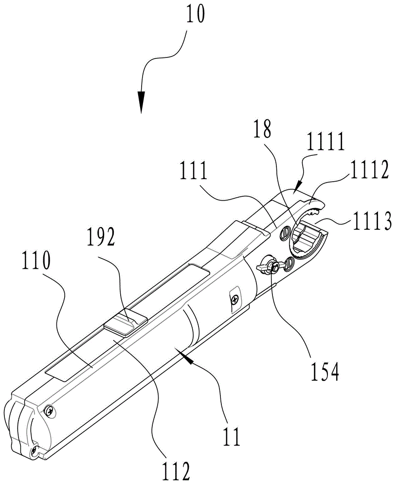
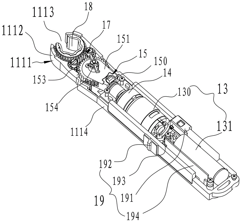
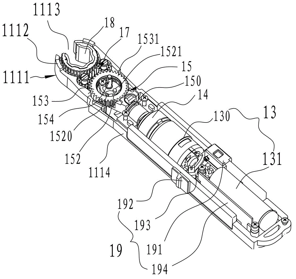
[0030] Please refer to Figure 1~3 , an electric wrench 10, including a housing 11, a power component 13, a reduction mechanism 14, a ratchet mechanism 15, a support transmission assembly 17, an open gear 18 and a control assembly 19.

[0031] The casing 11 is a "one"-shaped structure, which includes a main casing 110 extending in the longitudinal direction and a supporting casing 111 extending from one end of the main casing 110 . The power component 13 , the speed reduction mechanism 14 , the ratchet mechanism 15 , the supporting transmission assembly 17 and the split gear 18 are sequentially connected and housed in the housing 11 .

[0032] Please also refer to Figure 4 , in this embodiment, the main housing 110 includes a first outer housing 1101 and a second outer housing 1102, the ...


PUM


Abstract

An electric wrench comprises a casing, a power component, a ratchet mechanism, a supporting transmission module and an open gear. A mounting part is formed at one end of the casing. The power component, the ratchet mechanism, the supporting transmission module and the open gear are sequentially connected and accommodated in the casing, a threaded part penetrates the mounting part to reach the open gear, the supporting transmission module is connected with the open gear and drives the open gear to rotate, and accordingly the threaded part is tightened or unscrewed. The electric wrench can be used conveniently under the conditions that some bolts are too long, pipe nuts are screwed or an operating space is narrow, the ratchet mechanism serves as a reversing transmission mechanism, and power is provided by a motor. In the use process, operators only need to place the threaded part in a sleeve of the open gear and then start the power jaw wrench, the threaded part can be tightened or unscrewed on the conditions that the casing does not need rotating, and the electric wrench is simple and convenient to operate, small in working strength and high in working efficiency.

Description

technical field [0001] The invention relates to an electric tool, in particular to an electric wrench. Background technique [0002] Wrenches are widely used in daily life, and they are usually used to tighten or loosen screws and nuts. Commonly used wrenches include open-end wrenches and ratchet wrenches. Generally, the open-end wrench can put the threaded part into the side opening of the wrench, but in the tightening or loosening operation, after turning the threaded part by a small corner, the wrench needs to be removed from the threaded part, and then Put the wrench on the threaded part at another angle to continue turning. This process is usually repeated several times until the threaded part is completely tightened or loosened. Therefore, it is inconvenient to operate, and the open-end wrench is generally not suitable for use in some narrow spaces. The jaw of the ratchet wrench is usually a closed structure, so to tighten or loosen the threaded part, the ratchet wre...

Claims


Application Information

Patent Timeline
Patent Type & Authority Applications(China)
IPC IPC(8): B25B21/00B25B23/00
CPCB25B13/463B25B21/00B25B21/004
Inventor 陈亮周其伟陈武
Owner NANJING CHERVON IND
Why Eureka
Try Eureka