Heat exchanging device

A heat exchange device and heat exchanger technology are applied in the directions of household heating, heating methods, household heating, etc., to achieve the effect of improving heat exchange capacity and improving the distribution of air volume (wind speed).

Active Publication Date: 2014-07-09
三花新能源热管理科技(杭州)有限公司
View PDF7 Cites 5 Cited by
  • Summary
  • Abstract
  • Description
  • Claims
  • Application Information

AI Technical Summary

Problems solved by technology

In order to improve the heat exchange performance, air guide components are usually arranged in the cavity of the A-shaped heat exchang

Method used


Image

  • Heat exchanging device
  • Heat exchanging device
  • Heat exchanging device

Examples


Example Embodiment

[0039] The embodiments of the present invention are described in detail below. Examples of the embodiments are shown in the accompanying drawings, in which the same or similar reference numerals indicate the same or similar elements or elements with the same or similar functions. The embodiments described below with reference to the accompanying drawings are exemplary, and are intended to explain the present invention, but should not be construed as limiting the present invention.
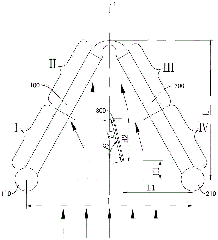
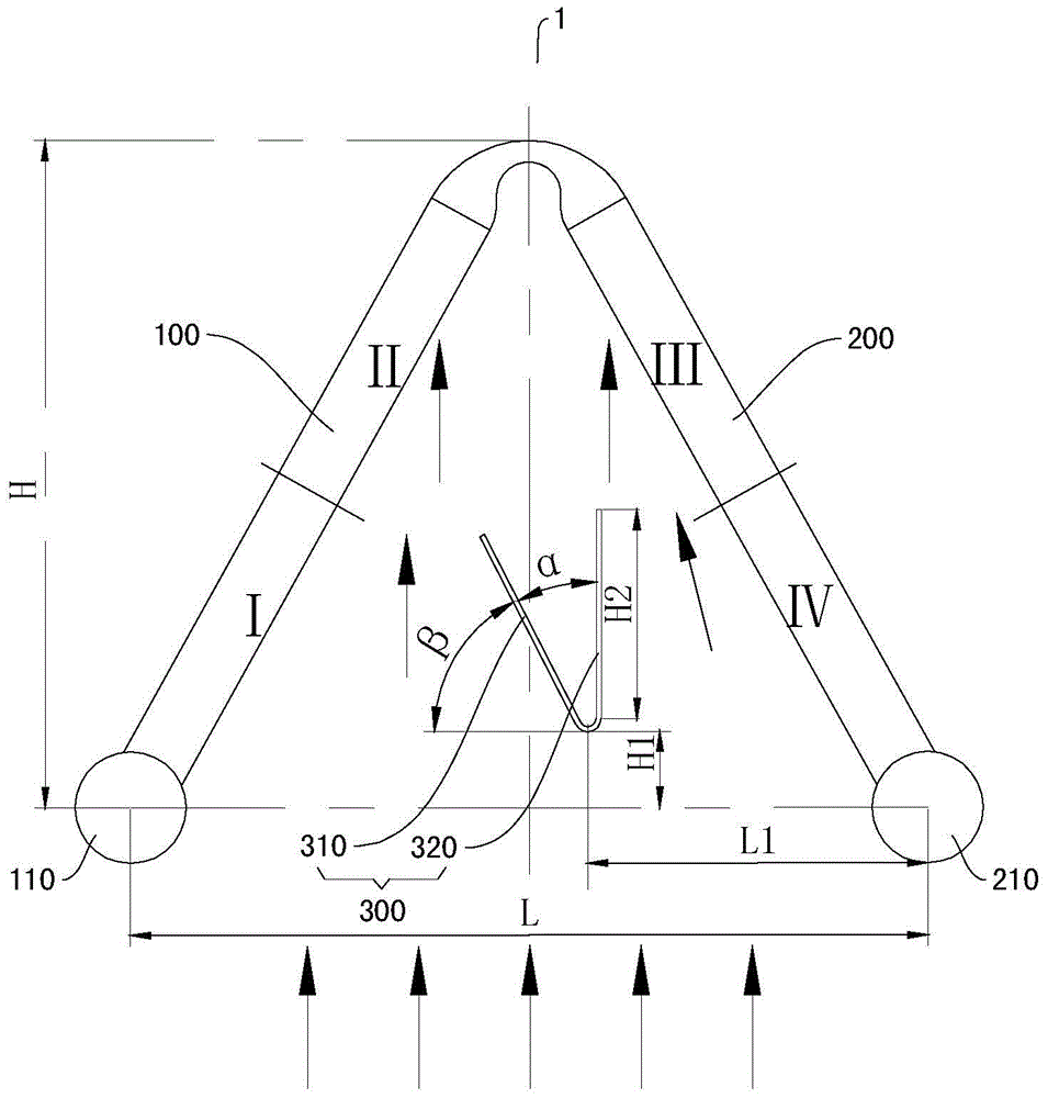
[0040] The uniformity of the wind speed (air volume) distribution on the surface of the heat exchange device has a significant impact on the heat exchange performance of the heat exchange device. Traditionally, for a generally inverted V-shaped heat exchange device, an air guiding component is arranged inside the heat exchange device so that the wind speed is evenly distributed on the heat exchange device. However, the inventor of the present application found that, due to the different heat transfer ...


PUM


Abstract

A heat exchanging device comprises a first heat exchanger, a second exchanger and an air guide member. The upper end of the first heat exchanger is connected tot the upper end of the second exchanger, the lower end of the first heat exchanger is separated from the lower end of the second heat exchanger. The lower end of the first heat exchanger is provided with a refrigerant inlet, and the lower end of the second heat exchanger is provided with a refrigerant outlet. The first heat exchanger and the second heat exchanger are formed by single planar bent heat exchangers or two independent planar heat exchanger. The air guide member is located between the first heat exchanger and the second heat exchanger and is closer to the second heat exchanger as compared with the first heat exchanger. According to a large V-shaped heat exchanger of an embodiment, the air guide member is arranged between the first heat exchanger and the second heat exchanger, distribution of air quantity can be optimized through the air guide member, the distribution of the air quantity matches with changes of heat exchanging parameters of the refrigerant, and heat exchanging capacity is improved.

Description

technical field [0001] The invention relates to the technical field of refrigeration, in particular to a heat exchange device. Background technique [0002] Heat exchange devices are used in a wide variety of applications, for example in air conditioners. Traditional heat exchange devices are usually flat. However, in some applications, it is necessary to bend the heat exchange device so as to divide the heat exchange device into a first heat exchanger part and a second heat exchanger part (usually called an A-shaped heat exchanger, the first The space between the heat exchanger part and the second heat exchange part is usually called the cavity of the heat exchange device). In use, the heat exchange device is placed in the box, and the wind flows upward from the bottom of the heat exchange device, and exchanges heat with the refrigerant in the heat exchange tube when passing through the first and second heat exchangers. In order to improve the heat exchange performance, ...

Claims


Application Information

Patent Timeline
IPC IPC(8): F25B39/00F24F13/30
Inventor 梁欣高强吴静
Owner 三花新能源热管理科技(杭州)有限公司
Why Eureka
Try Eureka