
Plasma processing chamber and gas injection device for the plasma processing chamber

A gas injection and processing device technology, applied in electrical components, discharge tubes, circuits, etc., can solve the problems of low utilization rate of reaction gas, waste of reaction gas, short dissociation time, etc. The effect of improving utilization efficiency and improving gas dissociation rate

Active Publication Date: 2016-08-17
ADVANCED MICRO FAB EQUIP INC CHINA
View PDF7 Cites 0 Cited by
  • Summary
  • Abstract
  • Description
  • Claims
  • Application Information

AI Technical Summary

Problems solved by technology

With the technology described in this method, the reaction gas is injected into the vacuum vessel in a straight line, and it is easy to diffuse outside the dissociation area of ​​the vacuum vessel and then be discharged from the vacuum vessel, resulting in the dissociation time of the reaction gas in the dissociation area being too short, dissociation Insufficient, resulting in low utilization rate of reaction gas, wasting reaction gas

Method used


Image

  • Plasma processing chamber and gas injection device for the plasma processing chamber
  • Plasma processing chamber and gas injection device for the plasma processing chamber
  • Plasma processing chamber and gas injection device for the plasma processing chamber

Examples


Embodiment Construction

[0023] In order to make the objectives, technical solutions, and advantages of the embodiments of the present invention clearer, the technical solutions in the embodiments of the present invention will be described clearly and completely in conjunction with the accompanying drawings in the embodiments of the present invention. Obviously, the described embodiments It is a part of the embodiments of the present invention, not all the embodiments. Based on the embodiments of the present invention, all other embodiments obtained by those of ordinary skill in the art without creative work shall fall within the protection scope of the present invention.

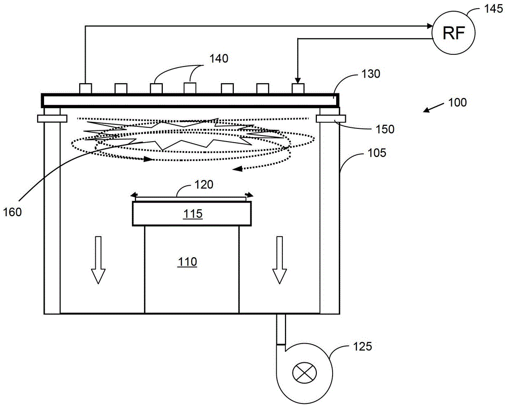
[0024] figure 1 It shows a schematic diagram of the reaction chamber structure of the plasma etching equipment where the gas injection device of the present invention is located, including the plasma reaction chamber device 100 according to an embodiment of the present invention. It should be understood that the reaction chamber devic...


PUM


Abstract

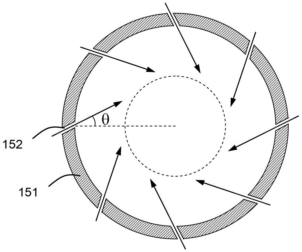
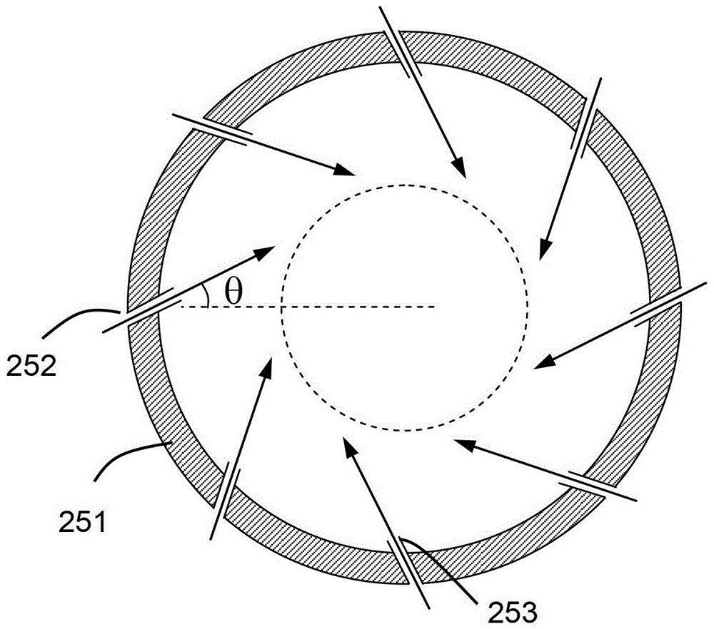
The invention discloses a plasma process chamber and a gas injection apparatus for the same. The inner wall of an annular gas injection pipeline is provided with a plurality of gas inlets, an acute angel is formed between a gas output direction and the direction directed towards the circle center of the annular gas injection pipeline by the gas inlet, and it is ensured that gas, after being injected into an reaction chamber, forms eddy current shaped distribution in a dissociation area, so that the gas sinking rate is delayed, the walk distance formed when the gas reaches a substrate is prolonged, and the gas is dissociated as much as possible in the dissociation area. Compared to a conventional gas inlet vertical to the inner wall of the annular gas injection pipeline, the advantages are as follows: the gas sinking rate is slowed, the gas dissociation rate is improved, the reaction gas utilization rate is improved, and at the same time, since the concentration of plasma in the reaction chamber rises, the etching rate is improved.

Description

Technical field [0001] The present invention relates to the technical field of gas supply for plasma etching equipment, in particular to the technical field of gas delivery for improving gas dissociation efficiency. Background technique [0002] Plasma reactors or reaction chambers are well known in the prior art and are widely used in the manufacturing industries of semiconductor integrated circuits, flat panel displays, light emitting diodes (LEDs), solar cells, etc. A radio frequency power is usually applied in the plasma chamber to generate and maintain plasma in the reaction chamber. Among them, there are many different ways to apply radio frequency power, and the design of each different way will lead to different characteristics, such as efficiency, plasma dissociation, uniformity, and so on. Among them, one design is the inductively coupled (ICP) plasma cavity. [0003] In an inductively coupled plasma processing chamber, a usually coil-shaped antenna is used to emit radi...

Claims


Application Information

Patent Timeline
Patent Type & Authority Patents(China)
IPC IPC(8): H01J37/32H01J37/02
Inventor 叶如彬倪图强
Owner ADVANCED MICRO FAB EQUIP INC CHINA
Learn More