Self-feeding-type permanent magnet eddy current speed regulator

A technology of eddy current and governor, which is applied in the field of mechanical transmission, can solve the problems of reduced performance, limited application range of high power, bulky and other problems, and achieve the effect of direct heat dissipation and improved power transmission efficiency

Active Publication Date: 2014-07-09
西安巨舟电子设备有限公司
View PDF10 Cites 5 Cited by
  • Summary
  • Abstract
  • Description
  • Claims
  • Application Information

AI Technical Summary

Problems solved by technology

This permanent magnet attraction is an unfavorable factor to the driving machine or load machine. In order to eliminate this magnetic attraction, the adjustment method of the first type of permanent magnet speed governor is set to a pair of permanent disks or a pair of conductor disks to displace in opposite directions, while The axial displacement mechanism that makes the moving rotor move in the opposite direction is relatively complicated. Although its products have realized this kind of motion control, the relatively complicated structure increases the unreliability factors sharply, and the performance against harsh environments is also sharply reduced.
The above-

Method used


Image

  • Self-feeding-type permanent magnet eddy current speed regulator
  • Self-feeding-type permanent magnet eddy current speed regulator
  • Self-feeding-type permanent magnet eddy current speed regulator

Examples


Embodiment Construction

[0034] The present invention will be described in further detail below in conjunction with the accompanying drawings.

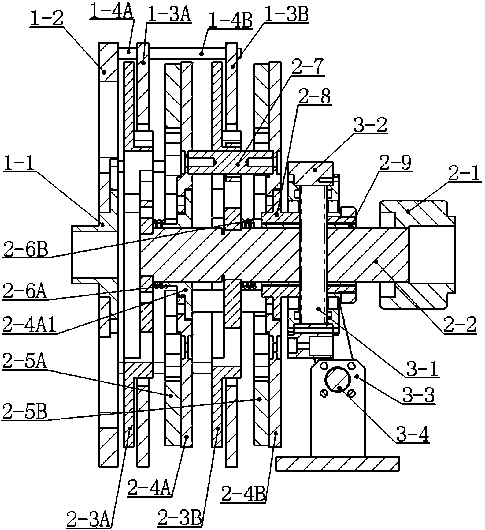
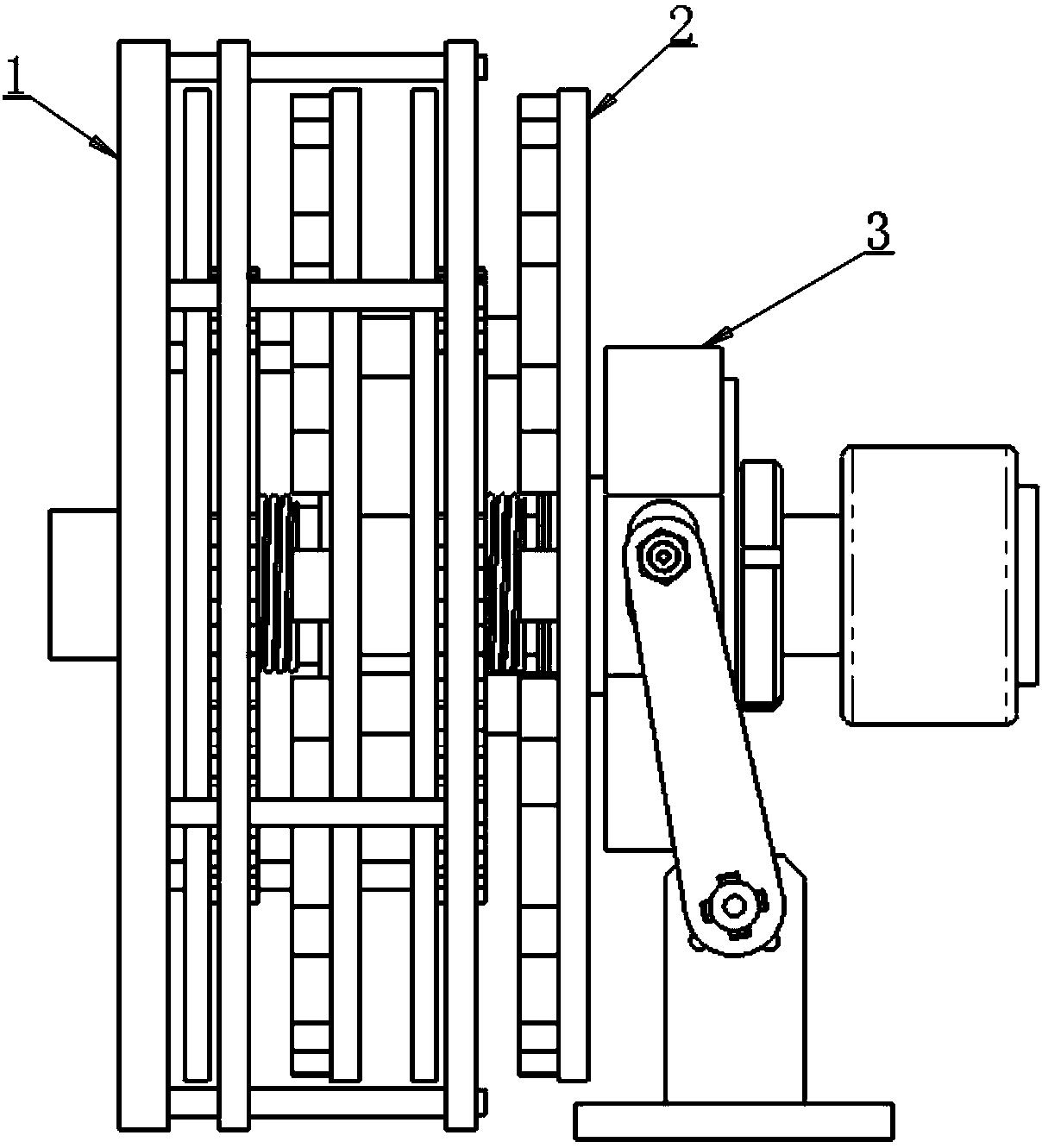
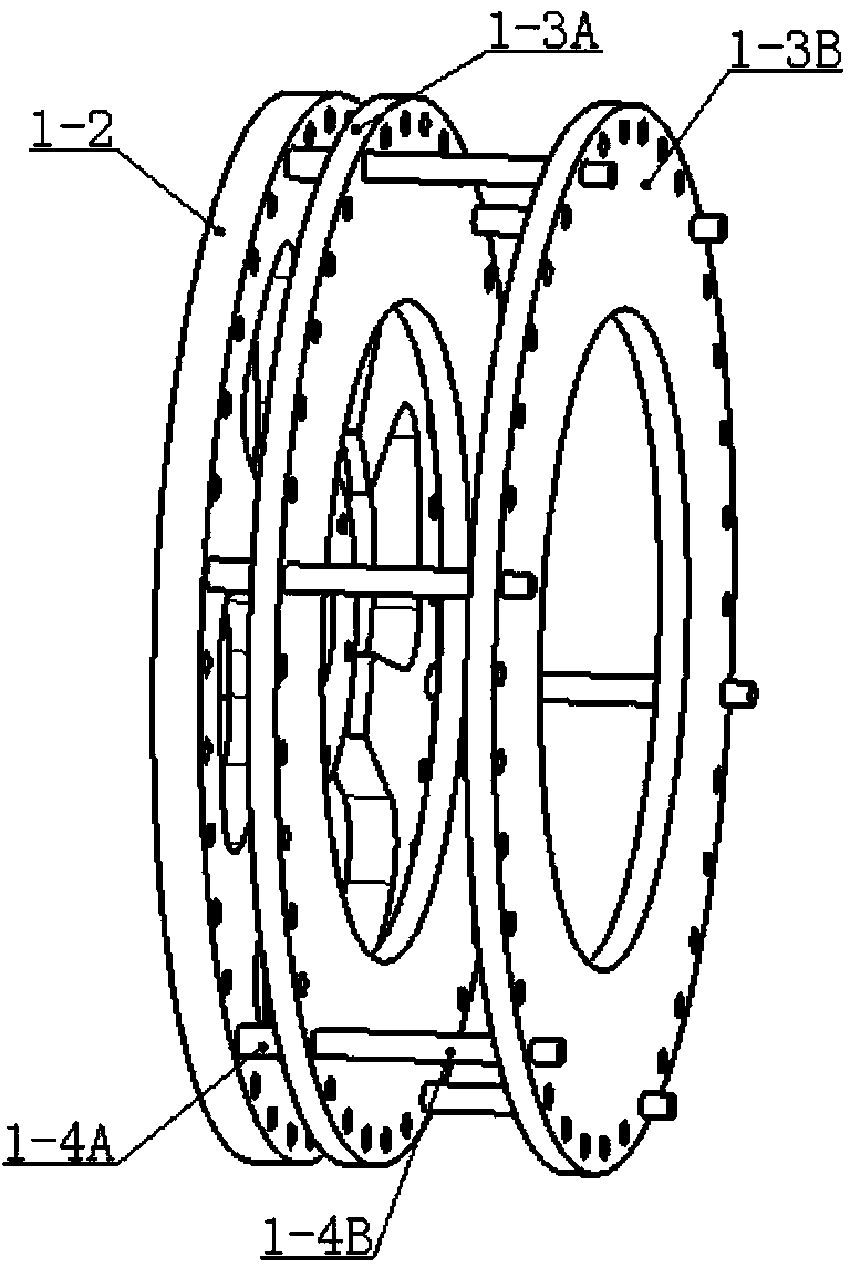
[0035] see Figure 1 to Figure 8 As shown, a self-feeding permanent magnet eddy current governor of the present invention includes a conductor rotor 1, a permanent magnet rotor 2 and a displacement adjustment mechanism 3; the conductor rotor 1 is fixed on the auxiliary shaft (not shown), and the permanent magnet rotor 2 includes an extended main shaft 2-2 arranged coaxially with the secondary shaft.

[0036] On the extension main shaft 2-2, permanent magnet rotor attached disks 2-3A and 2-3B are fixedly installed, and the permanent magnet rotor main disks 2-4A and 2-4B are sleeved on the extended main shaft 2-2; the permanent magnet rotor attached disk 2- 3A, 2-3B and permanent magnet rotor main discs 2-4A, 2-4B are arranged in parallel. The permanent magnet rotor attached disk 2-3A is provided with a central hole 2-3Z and a plurality of synchronous light r...


PUM


Abstract

The invention discloses a self-feeding-type permanent magnet eddy current speed regulator. The self-feeding-type permanent magnet eddy current speed regulator comprises an auxiliary shaft and an extension main shaft which are coaxially arranged; permanent magnet rotor main disks and permanent magnet rotor auxiliary disks are arranged on the extension main shaft in parallel in a pairwise mode, and the sides, facing the permanent magnet rotor auxiliary disks, of the permanent magnet rotor main disks are provided with permanent magnet groups; one permanent magnet rotor main disk and one permanent magnet rotor auxiliary disk form a permanent magnet disk pair; each permanent magnet rotor auxiliary disk on a permanent magnet rotor is fixedly installed on the extension main shaft; each permanent magnet rotor main disk is installed on the extension main shaft in a sleeved mode and can rotate synchronously with the corresponding permanent magnet rotor auxiliary disk; a through hole is formed in the center of a conductor disk fixedly connected with the auxiliary shaft, and the conductor disk is arranged on the periphery of the extension main shaft in a sleeved mode and located between the permanent magnet rotor auxiliary disks and the permanent magnet rotor main disks. According to the self-feeding-type permanent magnet eddy current speed regulator, one or more groups of magnetic fields with the intensity capable of being adjusted simply are flexibly established on the permanent magnet rotor, and axial permanent magnet attractive force with destructive power does not exist between the permanent magnet rotor and a conductor rotor which are not in contact with each other.

Description

【Technical field】 [0001] The invention belongs to the technical field of mechanical transmission, in particular to a self-feeding permanent magnet eddy current governor. 【Background technique】 [0002] The basic principle of the existing permanent magnetic coupling device is to use the relative motion between the conductor rotor and the permanent magnet rotor to induce a vortex magnetic field on the conductor rotor. . Using this mechanism, the power is transmitted from the power side to the load side in a non-contact manner. Its theoretical basis is classic and well-known, and the methods or prototypes for principle verification are diverse and simple, but mature engineering applications are rare. [0003] The first type of permanent magnet governor is disc-shaped, which adjusts the distance between the conductor rotor and the permanent magnet rotor, that is, adjusts the size of the air gap. The larger the air gap, the smaller the transmitted torque and the larger the slip...

Claims


Application Information

Patent Timeline
IPC IPC(8): H02K51/00H02K16/00
Inventor 马小安
Owner 西安巨舟电子设备有限公司
Why Eureka
Try Eureka