Feeding platform of inkjet coding machine

A technology of feeding platform and coding machine, which is applied in the direction of printing device, printing, etc., which can solve the problems of coding deviation, information coding area not directly below the nozzle, and poor initial placement of the conveyor belt, etc., to achieve good accuracy , Conducive to the effect of coding efficiency

Inactive Publication Date: 2014-07-16
CHINA CHENGDU ANIMAL HUSBANDRY IND BIOPHARM
View PDF8 Cites 2 Cited by
  • Summary
  • Abstract
  • Description
  • Claims
  • Application Information

AI Technical Summary

Problems solved by technology

[0004] In order to solve the problem in the above-mentioned prior art that the packaging boxes collide with each other during the movement of the conveyor belt or the initial position of the conveyor belt is not good, it is easy to cause that when the packaging box passes through the nozzle, the information coding area is not directly under the nozzle. , finally causing the obtained code to deviate from the designated spraying area, the invention provides a feeding platform for an inkjet coding machine

Method used


Image

  • Feeding platform of inkjet coding machine
  • Feeding platform of inkjet coding machine

Examples


Embodiment 1

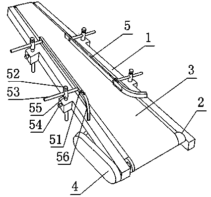
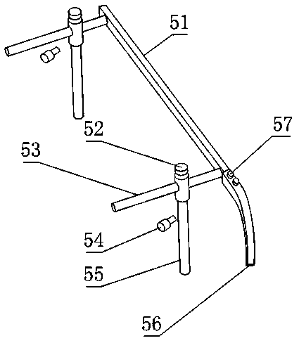
[0023] Such as figure 1 and figure 2 , the inkjet coding machine feeding platform provided by the present invention includes a platform frame 1, and the platform frame 1 is provided with at least two pulleys 2 parallel to each other, and a conveyor belt 3 is wound on the pulley 2. Two stoppers 5 on the frame 1 and located on different sides of the conveyor belt 3, the stoppers 5 include bar-shaped or plate-shaped stoppers 51 perpendicular to the axis of the pulley 2, and the stoppers 51 are fixedly connected with the axis A horizontal slide bar 53 parallel to the axis of the belt pulley 2, the platform frame 1 is also provided with a through hole whose axis is in the vertical direction, and the through hole is provided with a column 55 that fits with it in a clearance, and the platform frame 1 is also provided with a It is a height adjusting bolt 54 that is threaded, and the threaded end of the height adjusting bolt 54 is in contact with the column 55, and a slide bar hole i...

Embodiment 2

[0027] This embodiment is further limited on the basis of embodiment 1: as figure 1 and figure 2, in order to reduce the possibility that the extension length of the stopper 51 relative to the column 55 and the angle between the two will change automatically when the stopper 51 produces a pressing force with the packaging box, the horizontal slide on the limit device 5 There are two rods 53 , columns 55 , width adjustment bolts 52 and height adjustment bolts 54 , and two horizontal sliding rods 53 are respectively fixed at one end of the block 51 . The above setting makes any horizontal slide bar 53 all unable to rotate in the slide bar hole, and any horizontal slide bar 53 on the same block 51 is dependent on the sliding of another horizontal slide bar 53 relative to the column 55 connected thereto. Exercise to achieve the above technical effects.

Embodiment 3

[0029] This embodiment is further limited on the basis of embodiment 1: as figure 1 and figure 2 , also includes a pulley brake part 4, the pulley brake part 4 includes a motor and a belt, and the belt is wound between any one pulley 2 and the rotor of the motor. The provided pulley braking part 4 is used to brake the movement of the conveyor belt 3, and the structural form of a belt drive is adopted between the motor and the pulley 2, which has low cost, can obtain a large transmission ratio and prevents the conveyor belt 3 from jamming when the conveyor belt 3 is jammed. , the belt can protect the conveyor belt 3, the pulley 2 or the packing box by slipping.


PUM


Abstract

The invention discloses a feeding platform of an inkjet coding machine. The feeding platform of the inkjet coding machine comprises a platform rack, wherein at least two mutually parallel belt wheels are arranged on the platform rack, and the belt wheels are winded with conveyer belts. The feeding platform of the inkjet coding machine further comprises two limiting devices which are arranged on the platform rack and are located at different sides of the conveyor belts respectively, the limiting devices comprise baffle blocks, and horizontal sliding rods are fixedly connected to the baffle blocks; a through hole is further formed in the platform rack, and a vertical column is arranged in the through hole; a height adjusting bolt is further arranged on the platform rack, the end portion of the threaded end of the height adjusting bolt makes contact with the vertical column, sliding rod holes are formed above the vertical column, the horizontal sliding rods and the sliding rod holes are matched in a clearance fit mode; a width adjusting blot is further arranged on the vertical column, the end portion of the threaded end of the width adjusting blot makes contact with the horizontal sliding rods, the end portions of the baffle blocks are provided with arc-shaped portions respectively, and the two arc-shaped portions are located at the same side of the platform rack. By means of the feeding platform of the inkjet coding machine, accuracy of code printing positions and code printing efficiency of packing boxes are facilitated.

Description

technical field [0001] The invention relates to a printing and coating equipment for a medicine packaging box, in particular to a feeding platform for an inkjet coding machine. Background technique [0002] The coding principle of the inkjet coding machine is to apply a certain pressure to the ink in the system by controlling its internal gear pump or supplying compressed gas from its outside, so that the ink is ejected through a nozzle with an aperture of tens of microns, and the ink adheres to different positions on the product surface , Form the required various characters, patterns and other logos on the product. [0003] In the existing small and medium-sized pharmaceutical production enterprises, information such as the production date on the pharmaceutical packaging box needs to be sprayed or printed after the packaging box is sealed. In the prior art, the inkjet coding machine is generally equipped with a sensor, and when the packaging box passes through the nozzle,...

Claims


Application Information

Patent Timeline
Patent Type & Authority Applications(China)
IPC IPC(8): B41J11/00
CPCB41J3/407B41J11/007
Inventor 廖成斌邹学刚
Owner CHINA CHENGDU ANIMAL HUSBANDRY IND BIOPHARM
Why Eureka
Try Eureka