
Method for arranging a drive unit on a top element of a revolving door

A drive unit and revolving door technology, which is applied to revolving doors, wing leaf parts, door/window accessories, etc., and can solve the problem that installation measures cannot use revolving doors

Active Publication Date: 2017-10-13
DORMA GMBH & CO KG
View PDF9 Cites 0 Cited by
  • Summary
  • Abstract
  • Description
  • Claims
  • Application Information

AI Technical Summary

Problems solved by technology

Although the installation height of multi-pole motors can be limited, for example, by the height of the attic formed by the attic, these installation measures cannot in principle be used in every revolving door

Method used


Image

  • Method for arranging a drive unit on a top element of a revolving door
  • Method for arranging a drive unit on a top element of a revolving door
  • Method for arranging a drive unit on a top element of a revolving door

Examples


Embodiment Construction

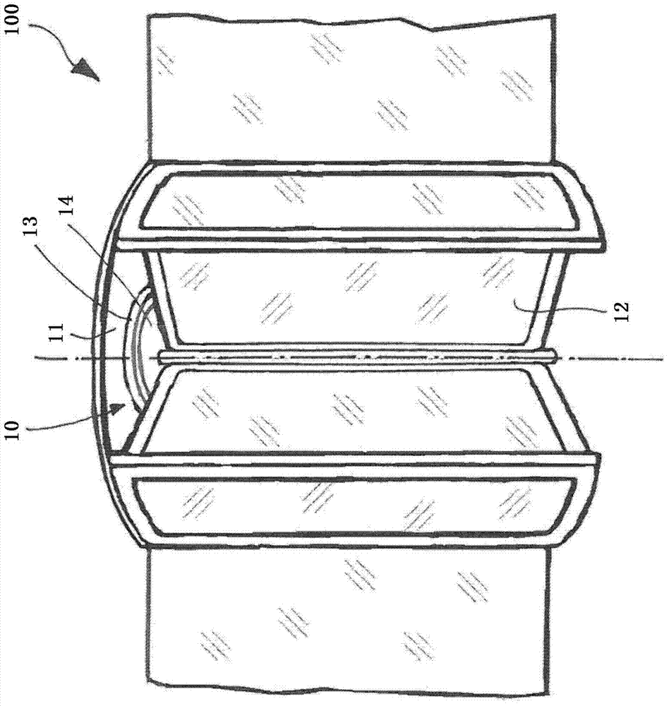
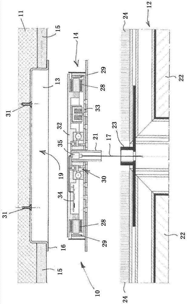
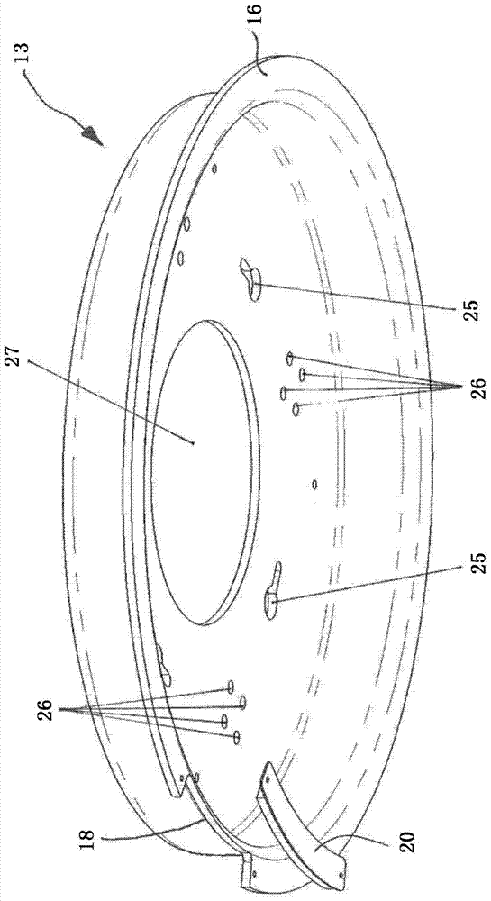
[0032] figure 1 An exemplary embodiment of a revolving door 100 is shown in a schematic perspective view, which is equipped in a retrofitted frame with a drive unit 10 which is arranged on the bottom side on a top element 11 of the revolving door 100 . The drive unit 10 is connected to the turnstile 12 of the revolving door 100 such that the drive unit 10 is located on the underside of the top element 11 and on the upper side of the turnstile 12 .

[0033] The drive unit 10 has a multi-pole motor 14 which has a flat cylindrical disk-shaped shape. The other components of the revolving door 100 and in particular the drive unit are not located on the upper side of the roof element 11 and the revolving door 100 can be integrated, for example, in a building facade which consists mainly of glass elements. In particular, the top element 11 of the revolving door 100 can be formed from a glass element, which can likewise be attached to the frame of the revolving door 100 in an additio...


PUM


Abstract

The method involves arranging a receiving vessel (13) at an underside of a ceiling element (11) so as to form at the underside of the ceiling element an installation cavity opening in a direction of an installation space of a turnstile (12). A flat-cylindrical, electronically commutated multipole motor (14) is inserted into the installation cavity to form a drive unit (10). An independent claim is included for drive unit assembly.

Description

technical field [0001] The invention relates to a method for arranging a drive unit in a revolving door, wherein the drive unit is arranged on a top element of the revolving door and serves to drive a turnstile of the revolving door. Background technique [0002] EP 2 072 737 A2 shows an arrangement of a drive unit in a revolving door, wherein the drive unit is arranged on the top element of the revolving door. The drive unit is arranged above the roof element and thus requires a large installation space above the revolving door, which is undesirable in newer building facades with revolving doors. Furthermore, there is the disadvantage that the drive unit requires a seal against the influence of weather, since the box-shaped installation space above the revolving door for receiving the drive unit is at least partially exposed to the weather, which requires complex sealing measures. . [0003] During the renovation of a building, the entrance area is often replaced by a new...

Claims


Application Information

Patent Timeline
Patent Type & Authority Patents(China)
IPC IPC(8): E05F15/608
CPCE05F15/608E05Y2900/132E06B3/90
Inventor 斯文·布施
Owner DORMA GMBH & CO KG
Features
  • Generate Ideas
  • Intellectual Property
  • Life Sciences
  • Materials
  • Tech Scout
  • Unparalleled Data Quality
  • Higher Quality Content
  • 60% Fewer Hallucinations
Learn More