
Efficient air guide device suitable for wind power generating or wind power pumping equipment

A wind guide device and wind power technology, which is applied to wind power engines, wind power generators at right angles to the wind direction, mechanical equipment, etc., can solve the problems of inability to respond to wind power in real time, far from the ideal value of wind power generation, and poor performance improvement. Achieve the effect of improving wind energy efficiency, increasing wind energy efficiency, and reducing wind speed limitation

Active Publication Date: 2014-07-16
南京水云运输研究院有限公司
View PDF6 Cites 16 Cited by
  • Summary
  • Abstract
  • Description
  • Claims
  • Application Information

AI Technical Summary

Problems solved by technology

There are also researchers who try to install wind blades in fixed air collectors to improve the efficiency of wind energy utilization, but because the air inlet and outlet are fixed, it is impossible to deal with the wind force from time to time in real time, and the efficiency improvement is still not good.
Studies have shown that the existing horizontal axis wind turbines have a wind energy utilization efficiency of about 30% to 40%; the current vertical axis wind turbines have a wind energy utilization efficiency of only about 20%, which is far from the ideal of wind power generation pursued by researchers. The value is very different

Method used


Image

  • Efficient air guide device suitable for wind power generating or wind power pumping equipment
  • Efficient air guide device suitable for wind power generating or wind power pumping equipment
  • Efficient air guide device suitable for wind power generating or wind power pumping equipment

Examples


Embodiment 1

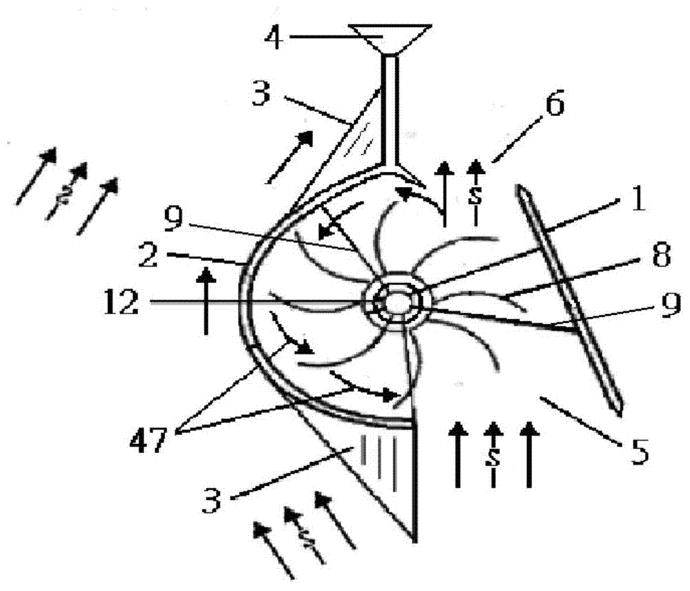
[0033] like figure 1 The shown high-efficiency wind guide device suitable for vertical axis wind power generators includes a central tower rod 12 on which rotatable wind blades 8 are arranged, and curved wind deflectors 1 and The curved wind baffle 2, the curved wind baffle 2 is in the shape of a semi-arc surface, an air inlet 5 is formed between the front end of the curved wind deflector 1 and the front end of the curved wind baffle 2, and the rear end of the curved wind deflector 1 is connected to the front end of the curved wind deflector 2. An air outlet 6 is formed between the rear ends of the arc-shaped wind-shielding plate 2, so that the natural wind from the outside flows from the air inlet 5 to the air outlet 6 to form a downstream wind 46 to push the wind blade 8 from front to back. The curved wind deflector 1 and the curved wind shield 2 are relatively rotatably connected to the central tower rod 12 through the support frames 9 at the upper and lower ends thereof, s...

Embodiment 2

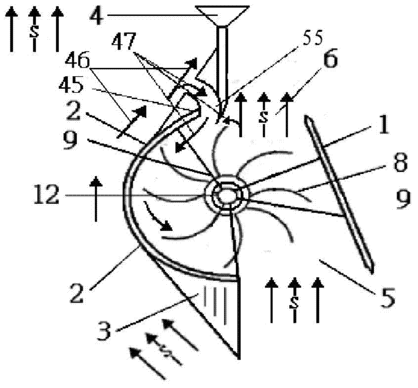
[0037] like figure 2 The high-efficiency air guiding device shown has the same structure as figure 1 The structure in is basically the same, except that figure 2 The return member in the middle is not the arc-shaped return plate 48, but the air-return pipe or return air slot 55 which is set in the arc-shaped transition of the rear section of the arc-shaped wind-shielding plate 2, which forms the return air, increases the headwind boost, and improves the wind energy efficiency. When embodiment 2 is working, the downstream wind 46, turbulent flow or disturbed wind on the outside of the arc-shaped wind-shielding plate 2 is introduced into the inside of the arc-shaped wind-shielding plate 2 through the air return pipe or the return air slot 55, and the wind blades 8 are moved from behind to Push forward to obtain the driving force against the wind, and turn the resistance against the wind into the power to improve the efficiency of wind energy utilization.

Embodiment 3

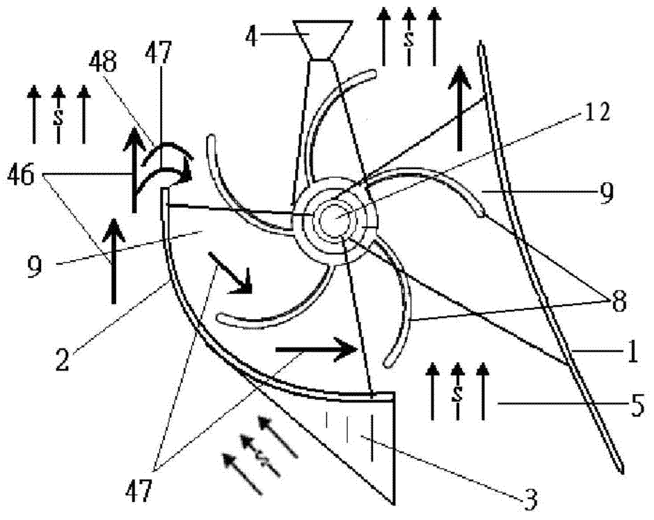
[0039] like image 3 The high-efficiency air guiding device shown has the same structure as figure 1 The structure is basically the same, the difference is that the arc-shaped wind-shielding plate 2 is in the shape of a 90-120° arc surface, and the return flow member is an arc-shaped return flow plate 48 arranged above the rear end point of the arc-surface wind-shielding plate 2 at intervals. And, the wind vane 4 is installed on the central tower pole 12 . When embodiment 3 works, the arc return plate 48 guides the downstream wind 46, turbulent flow or disturbed wind on the outside of the arc wind barrier 2 into the inner side of the arc wind barrier 2 to form the return wind 47, and the wind blades can also be 8Push forward from the back to obtain the driving force against the wind, and turn the resistance against the wind to assist.


PUM


Abstract

The invention discloses an efficient air guide device suitable for wind power generating or wind power pumping equipment. The efficient air guide device comprises a center tower pole provided with wind power blades capable of rotating. The two sides of each wind power blade are provided with a curved surface air guide plate and a cambered surface wind isolating plate respectively, wherein the curved surface air guide plates and the cambered surface wind isolating plates can rotate relative to the center tower pole. A wind inlet is formed between the front end of each curved surface air guide plate and the front end of each cambered surface wind isolating plate, and a wind outlet is formed between the rear end of each curved surface air guide plate and the rear end of each cambered surface wind isolating plate, so that the outside natural wind forms the free wind from the wind inlets to the wind outlets to push the wind power blades from front to back. The wind outlets are provided with backflow components. The backflow components guide some free wind to the inner side of the cambered surface wind isolating plates to form the backflow wind to push the blades from back to front, and therefore dead wind resistance is converted into backflow assistance. The efficient air guide device can greatly improve the wind power utilization efficiency and efficiently generate electricity at a low wind speed, and is particularly suitable for various perpendicular shaft type or horizontal shaft type wind power generators or wind power pumps, and limitation on the required minimum wind speed is reduced.

Description

technical field [0001] The invention relates to the field of wind energy development and application, in particular to a high-efficiency wind guiding device suitable for wind power generation or wind pumping equipment. Background technique [0002] At present, wind turbines are divided into horizontal axis type and vertical axis type. The advantages of vertical axis wind turbines are small blades, fast speed and low noise, but their power generation is limited, so they can only be used as small wind turbines. narrower. The advantage of the horizontal axis wind turbine is that it generates a large amount of power, and has become the mainstream of wind power generation today. However, it uses three-blade ultra-long pointed blades, making it dauntingly difficult to manufacture and install, and the noise it produces is also unbearable. Bear. [0003] Regardless of the horizontal-axis or vertical-axis wind turbines, they always try their best to increase their downwind driving ...

Claims


Application Information

Patent Timeline
IPC IPC(8): F03D3/04
CPCY02E10/74
Inventor 裴志勇吴卫国钟乾麟
Owner 南京水云运输研究院有限公司
Learn More