Efficient air guides for wind power or wind pumping installations
A wind guide device and wind power technology, applied to wind power engines, wind power generators at right angles to the wind direction, mechanical equipment, etc., can solve problems such as inability to respond to wind power in real time, far from the ideal value of wind power generation, and poor performance improvement. Achieve the effect of improving wind energy efficiency, increasing wind energy efficiency, and reducing wind speed limitation
- Summary
- Abstract
- Description
- Claims
- Application Information
AI Technical Summary
Problems solved by technology
Method used
Image
Examples
Embodiment 1
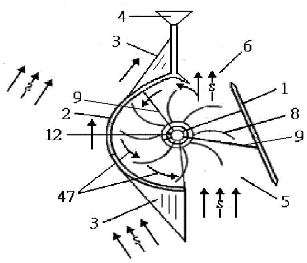
[0033] Such as figure 1 The shown high-efficiency wind guide device suitable for vertical axis wind power generators includes a central tower rod 12 on which rotatable wind blades 8 are arranged, and curved wind deflectors 1 and The curved wind baffle 2, the curved wind baffle 2 is in the shape of a semi-arc surface, an air inlet 5 is formed between the front end of the curved wind deflector 1 and the front end of the curved wind baffle 2, and the rear end of the curved wind deflector 1 is connected to the front end of the curved wind deflector 2. An air outlet 6 is formed between the rear ends of the arc-shaped wind-shielding plate 2, so that the natural wind from the outside flows from the air inlet 5 to the air outlet 6 to form a downstream wind 46 to push the wind blade 8 from front to back. The curved wind deflector 1 and the curved wind shield 2 are relatively rotatably connected to the central tower rod 12 through the support frames 9 at the upper and lower ends thereof...
Embodiment 2
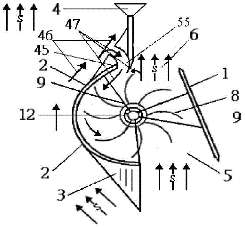
[0037] Such as figure 2 The high-efficiency air guiding device shown has the same structure as figure 1 The structure in is basically the same, except that figure 2 The return member in the middle is not the arc-shaped return plate 48, but the air-return pipe or return air slot 55 which is set in the arc-shaped transition of the rear section of the arc-shaped wind-shielding plate 2, which forms the return air, increases the headwind boost, and improves the wind energy efficiency. When embodiment 2 is working, the downstream wind 46, turbulent flow or disturbed wind on the outside of the arc-shaped wind-shielding plate 2 is introduced into the inside of the arc-shaped wind-shielding plate 2 through the air return pipe or the return air slot 55, and the wind blades 8 are moved from behind to Push forward to obtain the driving force against the wind, and turn the resistance against the wind into the power to improve the efficiency of wind energy utilization.
Embodiment 3
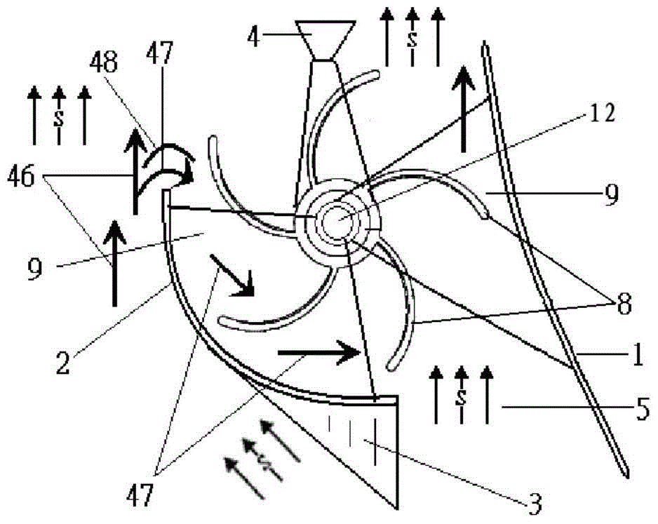
[0039] Such as image 3 The high-efficiency air guiding device shown has the same structure as figure 1 The structure is basically the same, the difference is that the arc-shaped wind-shielding plate 2 is in the shape of a 90-120° arc surface, and the return flow member is an arc-shaped return flow plate 48 arranged above the rear end point of the arc-surface wind-shielding plate 2 at intervals. And, the wind vane 4 is installed on the central tower pole 12 . When embodiment 3 works, the arc return plate 48 guides the downstream wind 46, turbulent flow or disturbed wind on the outside of the arc wind barrier 2 into the inner side of the arc wind barrier 2 to form the return wind 47, and the wind blades can also be 8Push forward from the back to obtain the driving force against the wind, and turn the resistance against the wind to assist.
PUM
 Abstract
Description
Claims
Application Information
 - R&D
- Intellectual Property
- Life Sciences
- Materials
- Tech Scout
- Unparalleled Data Quality
- Higher Quality Content
- 60% Fewer Hallucinations
Browse by: Latest US Patents, China's latest patents, Technical Efficacy Thesaurus, Application Domain, Technology Topic, Popular Technical Reports.
© 2025 PatSnap. All rights reserved.Legal|Privacy policy|Modern Slavery Act Transparency Statement|Sitemap|About US| Contact US: help@patsnap.com


