X-ray imaging device and imaging method thereof

An imaging device and X-ray technology, applied in the field of X-ray imaging, can solve problems such as inability to obtain information, time-consuming line array detectors, and inability to achieve DTS imaging.

Inactive Publication Date: 2013-03-20
SOUTHERN MEDICAL UNIVERSITY
View PDF9 Cites 25 Cited by
  • Summary
  • Abstract
  • Description
  • Claims
  • Application Information

AI Technical Summary

Problems solved by technology

[0005] Existing X-ray imaging equipment uses line array detectors in the process of collecting projection data, which is time-consuming. At the same time, because the distance between the ray source and the receiver is fixed, when the object to be detected is too small, whether it is a flat film image or CT In the tomographic image, the object only occupies a small part of the image, and most of the other image areas are useless information; when the detected object is too large, whether it is a plain film image or a CT tomographic image, part of the object information will occupy the entire image, other part information of the object will not be available
At the same time, the relative positions of the ray source and the receiver are also fixed, and the DTS imaging function cannot be realized

Method used


Image

  • X-ray imaging device and imaging method thereof
  • X-ray imaging device and imaging method thereof
  • X-ray imaging device and imaging method thereof

Examples


Embodiment Construction

[0035] Embodiments of the present invention will be described in detail below in conjunction with the accompanying drawings.

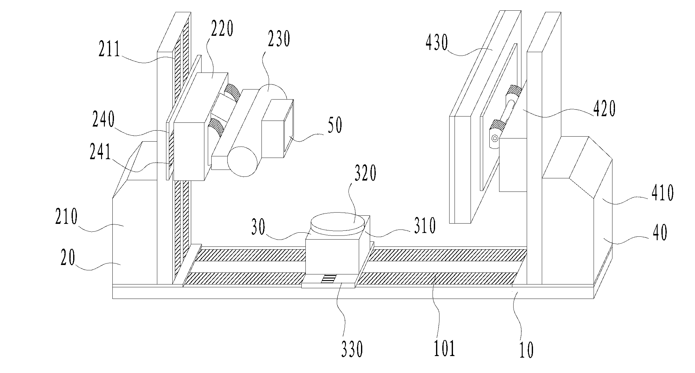
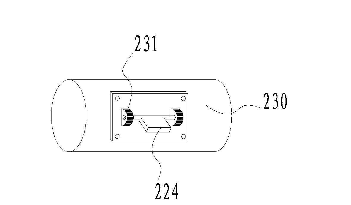
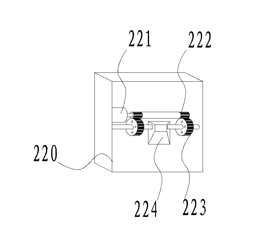
[0036] like figure 1 and 6 The shown X-ray imaging equipment includes a base 10, on which a slide rail 101 is arranged, and the slide rail 101 has a first end and a second end, and the radiation source control is sequentially arranged on the slide rail 101 along the direction from the first end to the second end. Device 20 , support control device 30 , receiver control device 40 . The radiation source control device 20 includes a first column 210 , a first pitching device 220 and a radiation source 230 . The first column 210 is slidably connected to the slide rail 101 . The first column 210 is provided with a first guide rail 211 . The first tilting motion device 220 is movably connected to the first guide rail 211 , and the radiation source 230 is movably connected to the first tilting motion device 220 . The support control device 30 includes a ta...


PUM


Abstract

The invention discloses an X-ray imaging device and an imaging method thereof. The X-ray imaging device comprises a base, a slide track is arranged on the base and provided with a first end and a second end, and the upper edge of the slide track is sequentially provided with a ray source control device, a support control device and a receiver control device. The ray source control device comprises a first column, a first pitching motion device and a ray source. The support control device comprises a table top support column and a rotary table top, wherein the table top support column can movably connected to the slide track, and a rotary shaft is arranged in the table top support column. The rotary table top is connected with the rotary shaft and is supported on the table top support column through the rotary shaft. The receiver control device comprises a second column, a second pitching motion device and a receiver. The X-ray imaging device and the imaging method integrates a perspective mode, a cone-beam round track CT mode, a cone-beam a cone-beam track CT mode and a digital theater system DTS mode.

Description

technical field [0001] The invention relates to the field of X-ray imaging, in particular to an X-ray imaging device and an imaging method thereof. Background technique [0002] X-rays have high penetrating power and are widely used in the fields of medical diagnosis and industrial inspection. Common X-ray imaging methods are X-ray and flat film. However, these two imaging methods can only obtain planar images in the projection direction, but cannot obtain depth information along the projection direction, that is, tomographic images. [0003] CT (computed tomography) imaging makes up for the shortcomings of the above two X-ray imaging methods. The X-ray tube and detector can be used to rotate around the detected object synchronously to obtain a sequence of projection images in the 360° range of the detected object. Using the reconstruction algorithm A series of two-dimensional tomographic images of the object can be obtained by processing these images, and these two-dimens...

Claims


Application Information

Patent Timeline
Patent Type & Authority Applications(China)
IPC IPC(8): A61B6/00G01N23/04
Inventor 周凌宏徐圆齐宏亮骆毅斌李慧君张广鹏甄鑫洪虹
Owner SOUTHERN MEDICAL UNIVERSITY
Why Eureka
Try Eureka