A detection device for the surface quality of a transparent optical element

A technology for detection devices and optical components, applied in measuring devices, material analysis through optical means, scientific instruments, etc., can solve problems such as inefficiency, failure to detect the surface quality of transparent optical components, and low detection efficiency of small-sized optical components , to achieve the effect of automatic displacement, fast detection speed and high degree of automation

Active Publication Date: 2016-07-06
TAIZHOU ZHENHAO AUTOMATION TECH
View PDF7 Cites 1 Cited by
  • Summary
  • Abstract
  • Description
  • Claims
  • Application Information

AI Technical Summary

Problems solved by technology

[0004] However, the above-mentioned detection device also has defects. For the surface detection of transparent optical elements below 7mm, the above-mentioned detection method cannot be effective, and there is no disclosure of any automatic double-sided detection of transparent optical elements in the prior art. equipment, and there is no equipment for testing the surface quality of transparent optical components pasted on plastic brackets. The current process is done by human eyes or with the help of an electron microscope, which leads to low detection efficiency for small-sized optical components

Method used


Image

  • A detection device for the surface quality of a transparent optical element
  • A detection device for the surface quality of a transparent optical element
  • A detection device for the surface quality of a transparent optical element

Examples


Embodiment Construction

[0022] The following are specific embodiments of the present invention and in conjunction with the accompanying drawings, the technical solutions of the present invention are further described, but the present invention is not limited to these embodiments.

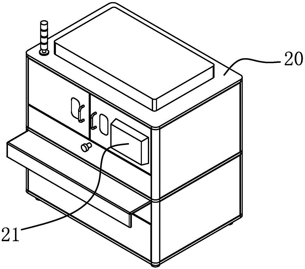
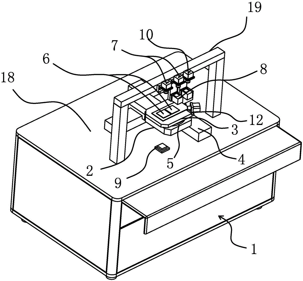
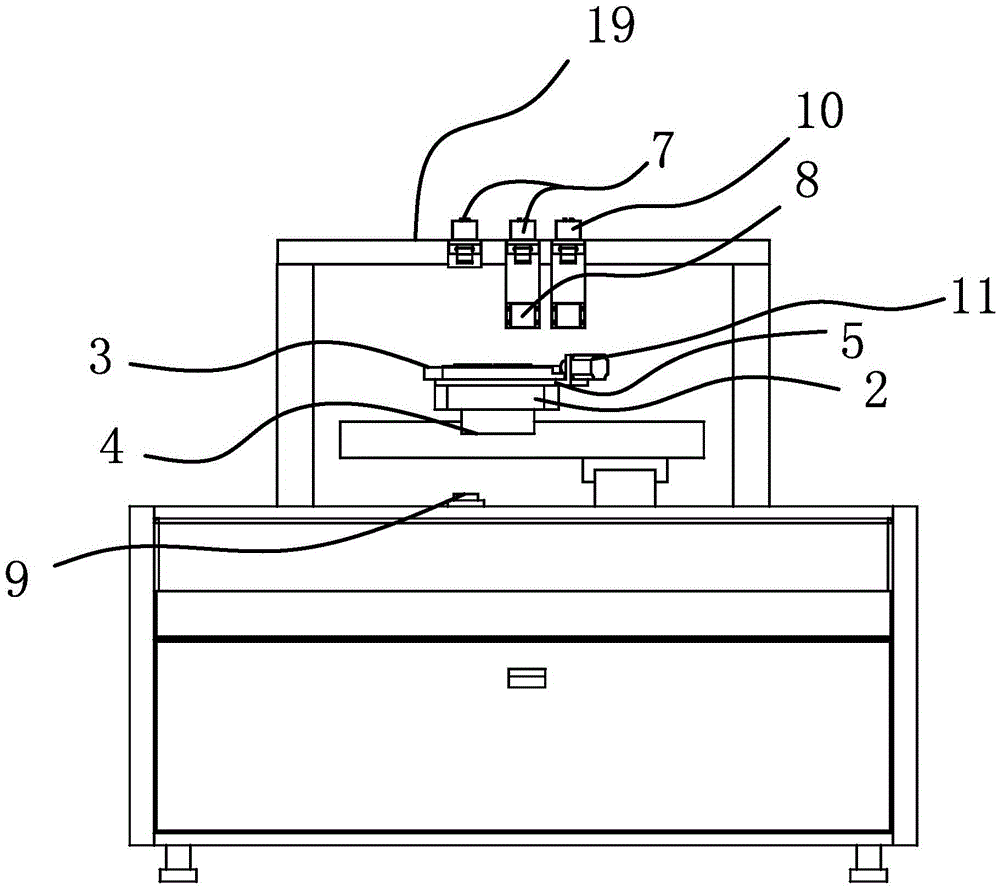
[0023] Such as figure 1 , figure 2 , image 3 , Figure 4 and Figure 5 As shown, the detection device includes a frame 1, a pallet 2 and a detection turntable 3, the pallet 2 is arranged on the frame 1, and there is a device between the pallet 2 and the frame 1 that enables the pallet 2 to move along the X axis and the Y axis. A two-axis drive mechanism 4 for axial movement, the detection turntable 3 is fixed on the top of the supporting plate 2 and the two can relatively rotate along the circumferential direction of the detection turntable 3, and the supporting plate 2 is provided with a rotation mechanism 5 that can drive the detection turntable 3 to rotate The two-axis driving mechanism 4 is an existing common mec...


PUM


Abstract

The invention provides a device for detecting surface quality of a transparent optical element, and belongs to the technical field of optical element detecting equipment. The device is used for solving the technical problem that no special detecting equipment is available for the surface detection of transparent optical elements with the diameter smaller than 7 mm. The detecting device comprises a rack, a carrier plate and a detecting turntable, wherein the carrier plate is arranged on the rack, a two-axis driving mechanism capable of driving the carrier plate to move along the X axis and the Y axis is arranged between the carrier plate and the rack, the detecting turntable is fixed above the carrier plate, the detecting turntable and the carrier plate can rotate oppositely along the circumferential direction of the detecting turntable, a rotating mechanism capable of driving the detecting turntable to rotate is arranged on the carrier plate, two detecting stations symmetrically distributed on the two sides of the rotating center of the detecting turntable are arranged on the detecting turntable, and corresponding detecting cameras, a first light source and a second light source are further arranged on the detecting turntable and are fixed on the rack. According to the device provided by the invention, the movement along the X axis or the Y axis can be automatically achieved by the two-axis driving mechanism so as to achieve automatic displacement and to improve the detecting efficiency.

Description

technical field [0001] The invention belongs to the technical field of optical element detection equipment, and in particular relates to a detection device for the surface quality of a transparent optical element. Background technique [0002] Transparent optical materials are very important components in various optical systems. Commonly used transparent optical materials include various types of glass, fused silica, and various crystal materials. When transparent optical components are used in many optical systems, they are often coated with some thin films such as anti-reflection coatings or high-reflection coatings on the surface, and sometimes they are closely attached to other optical component materials or plastic brackets to achieve certain specific functions. . All of the above applications put forward high requirements on the characteristics of related optical materials, such as high optical flatness on the surface of the material, no pollution, and no excessive ...

Claims


Application Information

Patent Timeline
Patent Type & Authority Patents(China)
IPC IPC(8): G01N21/958
Inventor 陈孟栅林觉鑫李超超万勇平
Owner TAIZHOU ZHENHAO AUTOMATION TECH
Why Eureka
Try Eureka