Optical path regulating and illuminating device

A lighting device and optical path adjustment technology, which is applied in optics, optical components, instruments, etc., can solve the problems of not being able to find images, affect the imaging quality, and inaccuracy, etc., and achieve simple structure, energy-saving light source optical path adjustment, practical and convenient effects

Inactive Publication Date: 2014-07-16
JIANGNAN UNIV
View PDF5 Cites 10 Cited by
  • Summary
  • Abstract
  • Description
  • Claims
  • Application Information

AI Technical Summary

Problems solved by technology

This method of visual inspection is generally not accurate enough, which often affects the image quality, and sometimes even cannot find the image.

Method used


Image

  • Optical path regulating and illuminating device
  • Optical path regulating and illuminating device
  • Optical path regulating and illuminating device

Examples


Embodiment Construction

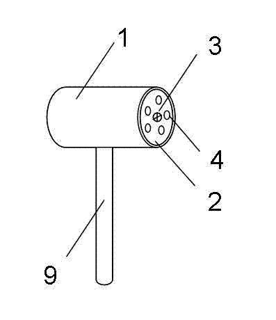
[0012] like figure 1 As shown, the downlight 1 is cylindrical, the head end surface 2 of the downlight 1 is circular, a laser 3 is arranged at the center of the circle, a group of LED lights 4 are evenly distributed around the laser 3, and the bottom of the downlight 1 is connected with a pole 9 .

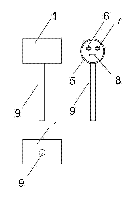
[0013] like figure 2 As shown, the tail end face 5 of the downlight 1 is provided with a laser switch 6 , an LED light switch 7 and a power interface 8 .

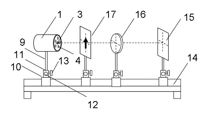
[0014] like image 3 As shown, the base 10 is placed on the guide rail 14 of the optical bench, and can slide linearly along the guide rail 14 of the optical bench. The upper surface of the base 10 is provided with a socket 11, and the downlight 1 is connected to the base 10 through the vertical rod 9 inserted into the socket 11. , the base 10 is provided with a lateral movement knob 12 and a height adjustment knob 13, wherein the lateral movement knob 12 is used to control the base 10 to make a small lateral movement in the ...


PUM


Abstract

The invention discloses an optical path regulating and illuminating device. The optical path regulating and illuminating device comprises a tube lamp, a base and an optical bench guide rail, wherein the tube lamp is cylindrical, the end face of the head portion of the tube lamp is circular, a laser device is arranged in the position of the circle center, a set of LED lamps are evenly distributed around the laser device, the tube lamp is connected with the base through a stand rod at the bottom of the tube lamp, the base is arranged on the optical bench guide rail, a transverse movement rotary knob and a height regulating rotary knob are arranged on the base, and the laser device is a cross curve laser device. Coaxial regulation of an optical path is achieved through cross-curve-shaped laser rays emitted by the laser device, the LED lamps serve as an experiment light source, and the optical path regulating and illuminating device is simple in structure, practical and convenient to use and has both the function of an energy-saving light source and the function of optical path regulation.

Description

technical field [0001] The invention belongs to the field of optical experimental instruments, in particular to an optical path adjustment and lighting device. Background technique [0002] When performing optical experiments such as lens focal length measurement on the optical bench, the coaxial adjustment of the lens and other optical devices placed on the guide rail of the optical bench must be performed to ensure accurate imaging. The method of visual inspection is generally used for coaxial adjustment, and the center of each optical device is at the same height and on the same straight line as the guide rail. This method of visual inspection is generally not accurate enough, which often affects the image quality, and sometimes even cannot find the image. Contents of the invention [0003] The technical problem to be solved by the present invention is to provide an optical path adjustment and lighting device that can be used not only as a light source but also for opt...

Claims


Application Information

Patent Timeline
Patent Type & Authority Applications(China)
IPC IPC(8): G02B27/34G02B27/36
Inventor 陈健朱纯高光华
Owner JIANGNAN UNIV
Why Eureka
Try Eureka