
G3 data forwarder and meter recording method for same
A technology of data transponder and meter reading method, which is applied in the direction of instruments, signal transmission systems, electrical signal transmission systems, etc. It can solve the problems that the carrier signal cannot reach the carrier energy meter and the quality of the power line communication channel is poor, so as to save investment and simplify Effect of on-site installation and reduced maintenance workload
- Summary
- Abstract
- Description
- Claims
- Application Information
AI Technical Summary
Problems solved by technology
Method used
Image

Examples
Embodiment Construction
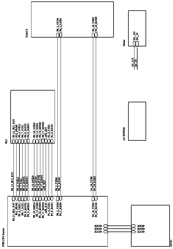
[0030] Such as figure 1 As shown, the present invention includes a main control MCU, a PLC circuit, an RS485 circuit, a serial port circuit and a power supply circuit. The main control MCU is connected to the PLC circuit through the serial port; the main control MCU is connected to the RS485 circuit through the 485 interface; the main control MCU is connected to the serial port circuit through the serial port. The power supply circuit provides power for the above-mentioned circuits, which includes an AC power supply circuit and a DC power supply circuit.
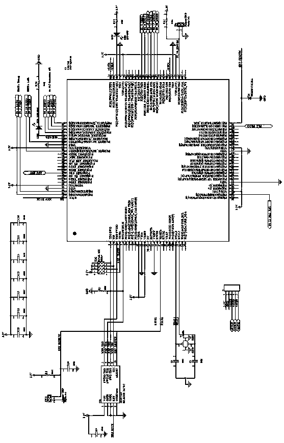
[0031] Such as figure 2 As shown, the main control MCU of the present invention adopts the microcontroller chip based on the ARM Cortex-M3 core of the model of NXP Company that is LPC1768.
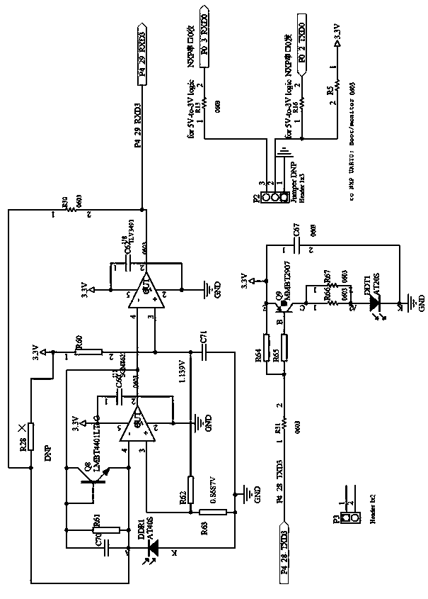
[0032] The main control MCU is connected to the UART0 interface through the AD port for debugging; it is connected to the UART3 interface through the serial port for receiving and sending infrared data; it is connected to the PLC base...
PUM
 Abstract
Description
Claims
Application Information