Roof ventilator

A technology of ventilator and air outlet, applied in the direction of roof, skylight/dome, roof covering, etc., to achieve the effect of saving labor, easy maintenance, and simplifying the electric deceleration mechanism.

Inactive Publication Date: 2014-07-23
锦州鹏翔电力轻钢设备有限公司
View PDF5 Cites 4 Cited by
  • Summary
  • Abstract
  • Description
  • Claims
  • Application Information

AI Technical Summary

Problems solved by technology

[0005] The technical problem to be solved by the present invention is to provide a reasonable structure, labor-saving opening of the valve plate, not easy to be damaged, easy to maintain, and can avoid the failure of the lighting function caused by dust accumulation on the valve plate of the original technology product, and can ensure long-term effective lighting effect. Low-cost roof ventilators

Method used


Image

  • Roof ventilator
  • Roof ventilator
  • Roof ventilator

Examples


Embodiment 1

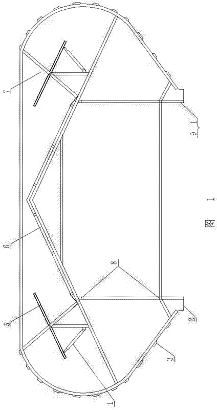
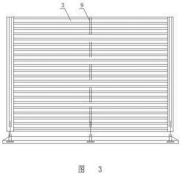
[0016] Such as figure 1 and image 3 As shown, the roof ventilator includes a structural support 1, and the structural support 1 is composed of a plurality of main frameworks 9 arranged side by side and longitudinal rods 8 connected between the plurality of main frameworks 9, on the upper part of the structural support 1 A ridge-shaped rain shield 6 is fixed, an outer guard plate 3 is fixed symmetrically on both sides of the structural support 1, and a sump 2 is symmetrically fixed between the bottom of both sides of the structural support 1 and the outer guard plate 3, and the rain shield 6 and the outer guard plate 3 are symmetrically fixed. A symmetrical air exhaust port 7 is formed between the outer guard plates 3 on both sides, and a centrally suspended valve plate 5 and an electric push rod 4 are respectively provided at the air exhaust port 7 on the structural support 1, and the middle part of the centrally suspended valve plate 5 is hinged. On the structural support 1...

Embodiment 2

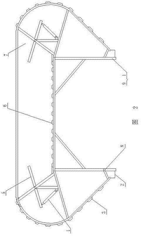
[0019] Such as figure 2 and image 3 As shown, the roof ventilator includes a structural support 1, and the structural support 1 is composed of a plurality of main frameworks 9 arranged side by side and longitudinal rods 8 connected between the plurality of main frameworks 9, on the upper part of the structural support 1 A horizontal rain shield 6 is fixed, an outer guard 3 is symmetrically fixed on both sides of the structural support 1, and a sump 2 is symmetrically fixed between the bottom of both sides of the structural support 1 and the outer guard 3, and the rain shield 6 and the outer guard 3 are symmetrically fixed. A symmetrical air exhaust port 7 is formed between the outer guard plates 3 on both sides, and a centrally suspended valve plate 5 and an electric push rod 4 are respectively provided at the air exhaust port 7 on the structural support 1, and the middle part of the centrally suspended valve plate 5 is hinged. On the structural support 1 , one side of the ...


PUM


Abstract

The invention discloses a roof ventilator which comprises a structure support, wherein a rain baffle is arranged on the upper portion of the structure support, outer protective plates and water collection chutes are symmetrically arranged on the two sides of the structure support, and symmetrical exhaust outlets are formed between the rain baffle and the outer protective plates on the two sides. The roof ventilator is characterized in that a middle suspension valve plate and an electric push rod are arranged on the structure support and located at the position of each exhaust outlet, the middle of each middle suspension valve plate is hinged to the structure support, one side of each middle suspension valve plate is connected with the corresponding electric push rod, and each exhaust outlet can be closed by the corresponding middle suspension valve plate driven by the corresponding electric push rod after the middle suspension valve plate overturns. The roof ventilator has the advantages that the structure is reasonable, opening can be achieved effortlessly, damage does not occur easily, maintenance is convenient, external rain, snow and sand can be prevented from flowing backwards into a roof ventilation opening along with wind when the valve plates are opened, a closed shell communicated with a building can be formed when the valve plates are closed, the ventilation quantity adjusting function and the external air backflow adjusting function can be achieved by adjusting the opening degree of the valve plates, the long-term and effective lighting effect can be guaranteed, and manufacturing cost is low.

Description

technical field [0001] The invention relates to building environment energy-saving products, in particular to a roof ventilator. Background technique [0002] The roof ventilator is a wind-shielding skylight in the form of a light steel color plate structure developed with the development of the application of architectural light steel color plate technology. Domestic architectural design has formed multiple versions of technical standards based on the roof ventilator technology, including "Ventilation Skylight" , "Selection and Installation of Roof Natural Ventilators", etc., are widely used in architectural design. [0003] Due to the limitation of domestic building material technology and mechanical technology during the product development period, the roof ventilator technology is limited to the application of natural ventilation function, and the product has many application technical problems: 1. Set the opening and closing valve plate to control the vent at the bottom...

Claims


Application Information

Patent Timeline
Patent Type & Authority Applications(China)
IPC IPC(8): E04D13/03E04D13/035
Inventor 单连勤鲁宇新单晓晴杨立年
Owner 锦州鹏翔电力轻钢设备有限公司
Why Eureka
Try Eureka