A foldable door stopper
A technology for folding doors and door stoppers, which is applied to building fastening devices, wing leaf fastening devices, buildings, etc. It can solve the problems of affecting the beauty of indoor layout, hindering cleaning work, accidental tripping, etc., and saves labor in the installation process Fast, simple and novel structure, prolonging the service life
- Summary
- Abstract
- Description
- Claims
- Application Information
AI Technical Summary
Problems solved by technology
Method used
Image

Examples
Embodiment 1
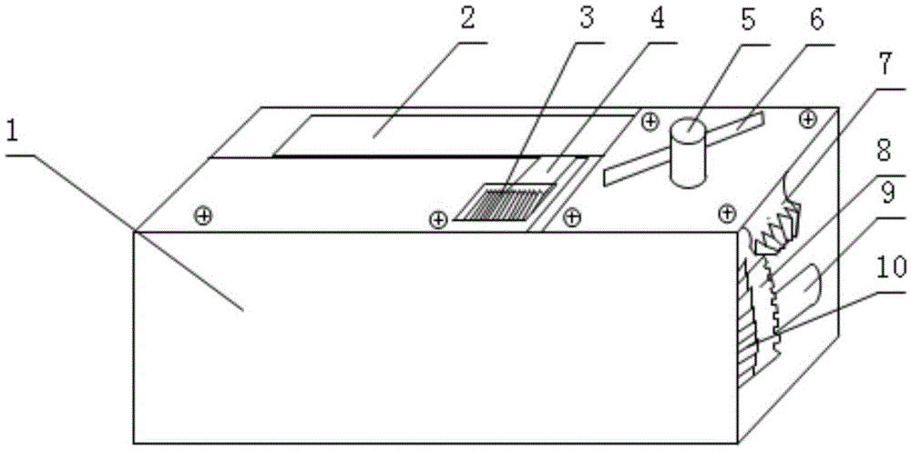
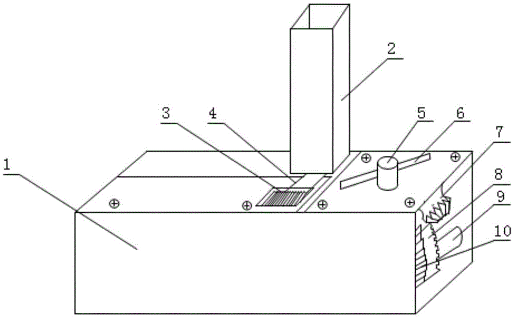
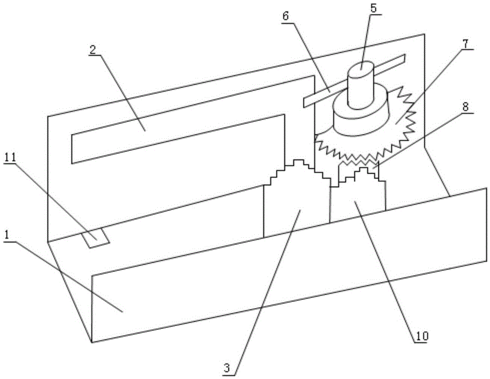
[0031] A foldable door stopper, such as figure 1 , 2 , 3, it is characterized in that it consists of two steering gears, two ordinary gears, two rotating shafts and a rotating part, the two steering gears are steering gear I7 and steering gear II8, and the two Ordinary gears are gear I10 and gear II3, and the two rotating shafts are rotating shaft 4 and supporting shaft 9, and supporting shaft 9 is fixed on the inner wall of housing 1, and the rotating parts are composed of rotating shaft 5 and rotating rod 6; The gear I7 is connected to the rotating rod 6 through the rotating shaft 5, the rotating rod 6 is arranged in a rod shape, the steering gear I7 is installed on the upper wall of the housing 1 through the rotating shaft 5, and the steering gear II8 and the gear I10 are coaxially fixed on the supporting shaft 9 , the steering gear II8 and the gear I10 are fixedly connected, the gear II3 is fixedly connected through the rotating shaft 4, the rotating shaft 4 is fixedly co...
Embodiment 2
[0035] A foldable door stopper, such as figure 1 , 2 , 3, it is characterized in that it consists of two steering gears, two ordinary gears, two rotating shafts and a rotating part, the two steering gears are steering gear I7 and steering gear II8, and the two Ordinary gears are gear I10 and gear II3, and the two rotating shafts are rotating shaft 4 and supporting shaft 9, and supporting shaft 9 is fixed on the inner wall of housing 1, and the rotating parts are composed of rotating shaft 5 and rotating rod 6; The gear I7 is connected with the rotating shaft 5 and the rotating rod 6, the rotating rod 6 is spherical, the steering gear I7 is installed on the upper wall of the housing 1 through the rotating shaft 5, and the steering gear II8 and the gear I10 are coaxially fixed on the support shaft 9, The steering gear II8 and the gear I10 are fixedly connected, the gear II3 is fixedly connected through the rotating shaft 4, and the rotating shaft 4 is fixedly connected with the...
Embodiment 3
[0039] A foldable door stopper, such as figure 1 , 2 , 3, it is characterized in that it consists of two steering gears, two ordinary gears, two rotating shafts and a rotating part, the two steering gears are steering gear I7 and steering gear II8, and the two Ordinary gears are gear I10 and gear II3, and the two rotating shafts are rotating shaft 4 and supporting shaft 9, and supporting shaft 9 is fixed on the inner wall of housing 1, and the rotating parts are composed of rotating shaft 5 and rotating rod 6; The gear I7 is connected to the rotating rod 6 through the rotating shaft 5, the rotating rod 6 is arranged as a butterfly, the steering gear I7 is installed on the upper wall of the housing 1 through the rotating shaft 5, and the steering gear II8 and the gear I10 are coaxially fixed on the supporting shaft 9 , the steering gear II8 and the gear I10 are fixedly connected, the gear II3 is fixedly connected through the rotating shaft 4, the rotating shaft 4 is fixedly co...
PUM
 Abstract
Description
Claims
Application Information
 - R&D
- Intellectual Property
- Life Sciences
- Materials
- Tech Scout
- Unparalleled Data Quality
- Higher Quality Content
- 60% Fewer Hallucinations
Browse by: Latest US Patents, China's latest patents, Technical Efficacy Thesaurus, Application Domain, Technology Topic, Popular Technical Reports.
© 2025 PatSnap. All rights reserved.Legal|Privacy policy|Modern Slavery Act Transparency Statement|Sitemap|About US| Contact US: help@patsnap.com