tofd test block automatic scanning device

A technology of scanning device and test block, which is applied in the field of ultrasonic testing, can solve problems such as easy bending and inaccuracy of maps, map errors, unfavorable data interpretation and measurement, etc., achieve stable data collection, convenient operation, and avoid incomplete scanning Effect

Active Publication Date: 2016-06-01
宁波市劳动安全技术服务有限公司
View PDF6 Cites 2 Cited by
  • Summary
  • Abstract
  • Description
  • Claims
  • Application Information

AI Technical Summary

Problems solved by technology

Moreover, in order to ensure the scanning accuracy, the scanning frame needs to walk on a plane, which brings very strict dimensional accuracy requirements to the processing of grooves
[0009] The existing manual scanning methods are not only labor-intensive, but also the quality of debugging and calibration is affected by many factors, the data is easy to be lost and distorted, and the map is easy to bend and not straight, which is not conducive to data interpretation and measurement. There is an error with the actual situation

Method used


Image

  • tofd test block automatic scanning device
  • tofd test block automatic scanning device
  • tofd test block automatic scanning device

Examples


Embodiment 1

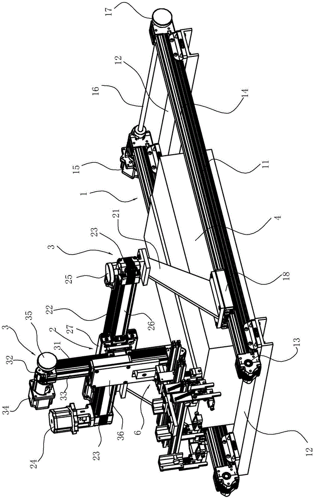
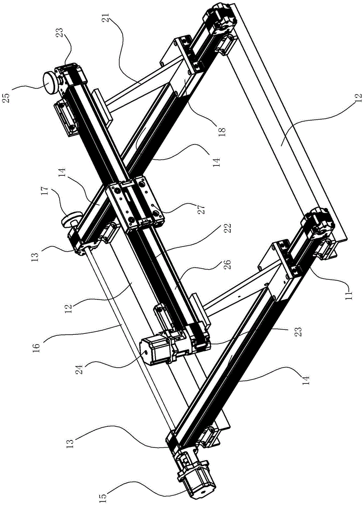
[0030] Such as Figure 1 to Figure 7 As shown, the TOFD test block automatic scanning device includes:

[0031] The scanning frame is sleeved on the outside of the test block 4, and includes a bottom frame formed by two parallel first rails 11 and connecting plates 12 connected to the two first rails. Two first rails 11 Arranged along the length direction (scanning direction) of the test block, the two first guide rails 11 are also components of the first module in the three-dimensional linear motion module in this embodiment.

[0032] The three-dimensional linear motion module is used to drive the connecting seat 6 to move in the X, Y, and Z three-dimensional directions. The three-dimensional linear motion modules in this embodiment are all linear motion modules with a synchronous belt structure.

[0033] The first linear motion module 1 is used to drive the connecting seat 6 to move along the X axis to scan the test block. It includes two first guide rails 11 shared with the sca...

Embodiment 2

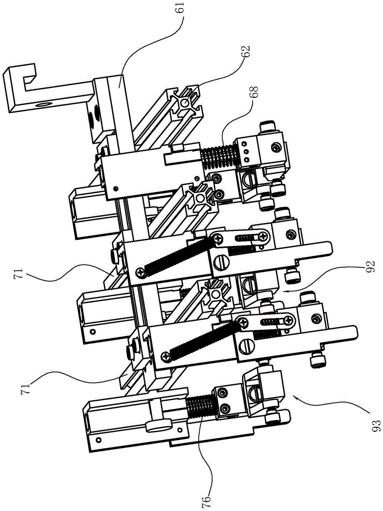
[0049] Such as Figure 8 As shown, the third linear motion module 3'in this embodiment adopts a ball screw structure. It includes a bracket 31' arranged on the second sliding block 27, and the bracket 31' is provided with a ball screw 32'. In this embodiment, there are two guide rails 33' on both sides of the screw, and a third sliding block 34' The third sliding block 34' is fixedly connected with the screw nut of the ball screw 32' and is slidably connected with the two guide rails 33'. The third transmission motor 35' is arranged on the bracket 31' and is coaxially connected with the lead screw 34'.

[0050] Compared with the third linear motion module of the synchronous belt structure in the embodiment 1, the third linear motion module of the ball screw structure in this embodiment has more accurate upper and lower positioning of the probe group, and has a power-off self-locking Features.

[0051] The rest of the content is the same as in Embodiment 1, and will not be repeate...


PUM


Abstract

The invention relates to an automatic scanning device of a time-of-flight diffraction (TOFD) test block. The automatic scanning device comprises a scanning rack. The automatic scanning device is characterized in that the scanning rack is arranged on the outer side of the test block in a sleeved mode and is formed by X-axis, Y-axis and Z-axis three-dimensional linear movement modules; the X direction is the movement direction when the test block is scanned; a slide block on the X-axis linear movement module is connected with an encoder; an input shaft of the encoder is coupled to a non-moving part on which the scanning rack is arranged, the test block surface and the surfaces of other non-moving objects through rollers; a slide block on the Z-axis linear movement module is connected with a connection base; a first probe group is arranged on the connection base; a first elastic element capable of enabling the first probe group to resist against the surface of the test block is also arranged between the connection base and the first probe group; and the X-axis linear movement module is driven by adopting a motor. The scanning rack is arranged on the periphery of the test block, so that the automatic scanning device is stable in data collection, smooth in atlas without data loss, and convenient to operate.

Description

Technical field [0001] The invention relates to the field of ultrasonic detection, in particular to an automatic scanning device for a TOFD test block. Background technique [0002] TOFD technology is a detection technology based on diffraction signals. It uses the principle that waves continue to propagate through scattering after encountering obstacles or small holes. Two broadband narrow pulse probes are used for detection. The probe is relative to the weld. The center line is arranged symmetrically. The transmitting probe generates an unfocused longitudinal wave beam incident at a certain angle into the inspected workpiece, part of the beam propagates along the near surface and is received by the receiving probe, and part of the beam is reflected by the bottom surface and then received by the receiving probe. The receiving probe determines the position and height of the defect by receiving the diffraction signal from the tip of the defect and its time difference. TOFD techn...

Claims


Application Information

Patent Timeline
Patent Type & Authority Patents(China)
IPC IPC(8): G01N29/265
Inventor 陈定岳郑祥明王杜陈虎黄辉胡杰沈建民鲍伟光牛亚平许波吴文祥黄莎露
Owner 宁波市劳动安全技术服务有限公司
Why Eureka
Try Eureka