
Force feedback type touch panel device

A touch panel and force feedback technology, applied in the direction of instruments, electrical digital data processing, electrical components, etc., to achieve the effect of inhibiting loosening and easing the suppression of amplitude

Inactive Publication Date: 2017-04-12
SMK CO LTD
View PDF4 Cites 0 Cited by
  • Summary
  • Abstract
  • Description
  • Claims
  • Application Information

AI Technical Summary

Problems solved by technology

In all these cases, in order to transmit the vibration to the operator, it is necessary to expose the surface of the touch panel to the outside of the device.

Method used


Image

  • Force feedback type touch panel device
  • Force feedback type touch panel device
  • Force feedback type touch panel device

Examples


Embodiment Construction

[0035] use Figure 1 to Figure 6 A force feedback type touch panel device 1 according to an embodiment of the present invention will be described.

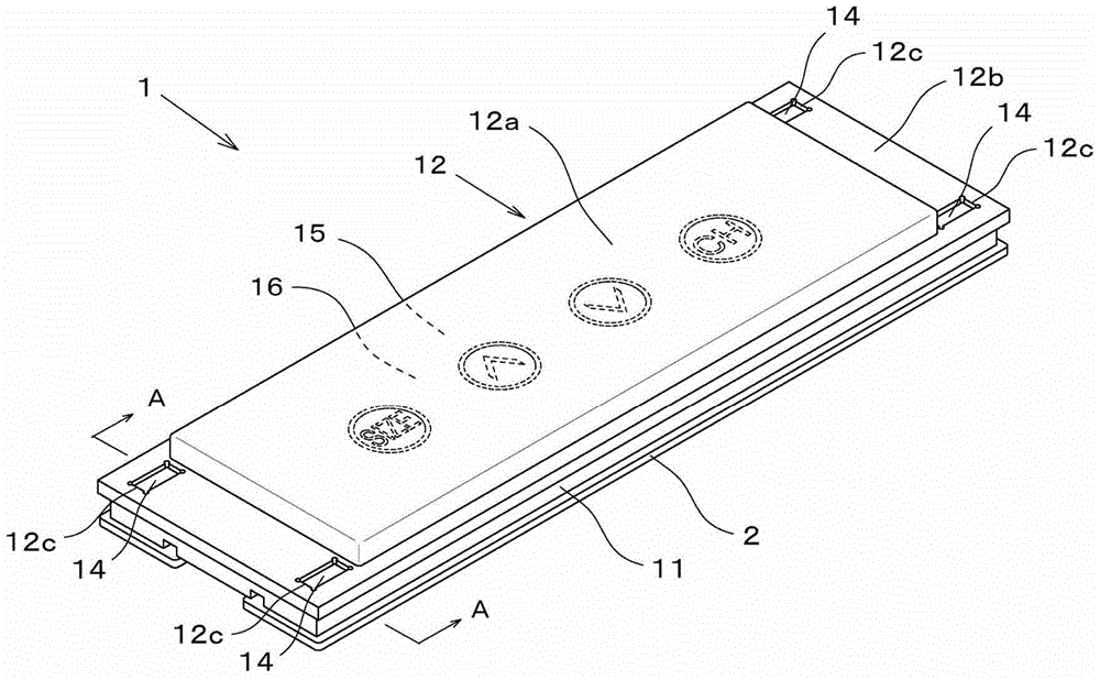
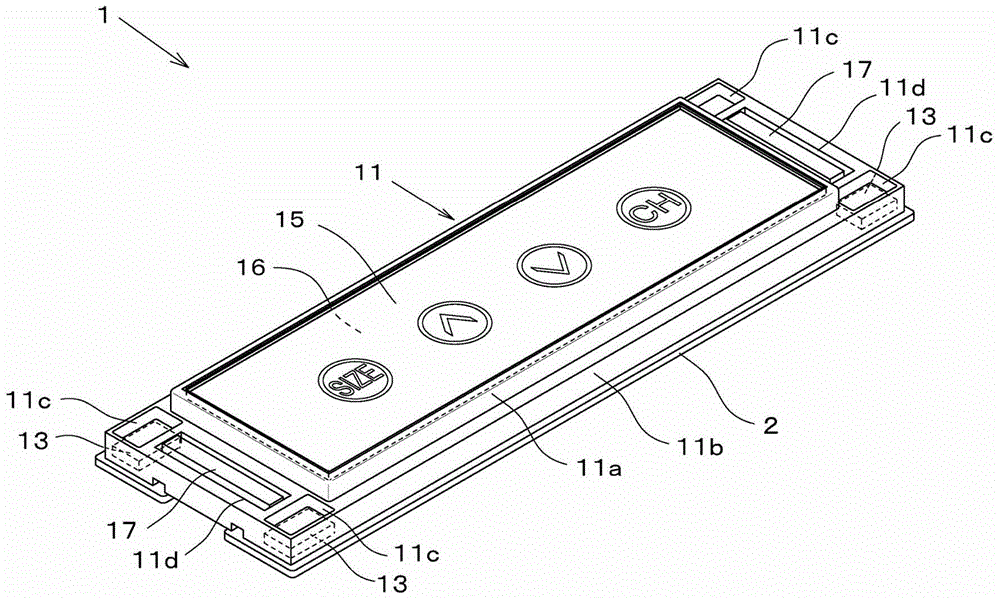
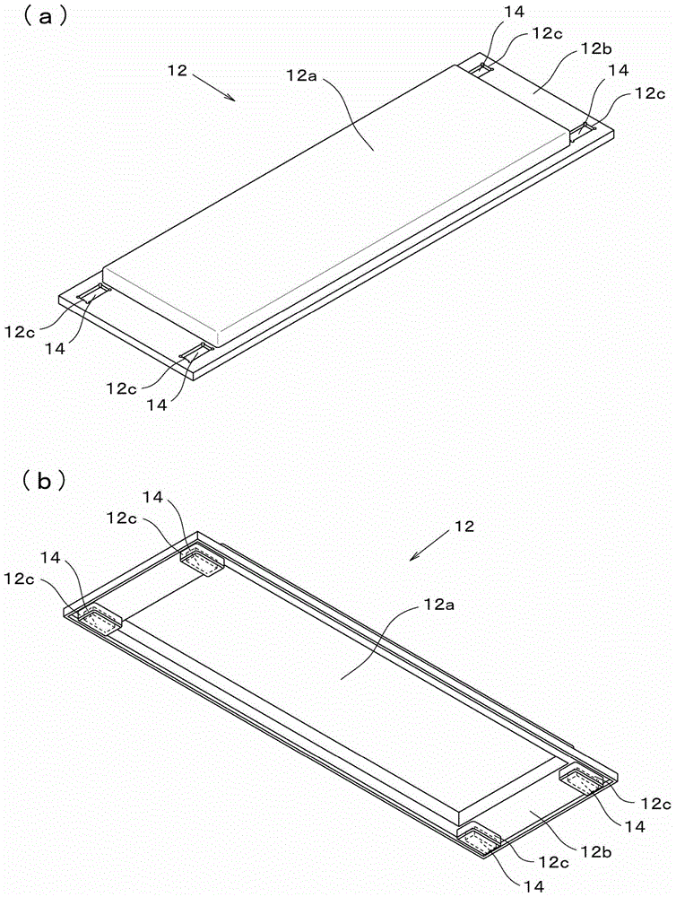
[0036] figure 1 The appearance of this embodiment is shown. In this embodiment, the printed wiring board 2, the base member 11, and the cover member 12 are sequentially stacked. The cover member 12 has the flat-plate part 12a piled up and formed in planar shape, and the extended part 12b around it. A capacitive touch panel 15 as a touch panel and a liquid crystal display device 16 as a display device are held by the base member 11 under the flat plate portion 12 a (details will be described later). Both the cover member 12 and the capacitive touch panel 15 are transparent, and characters or symbols such as "SIZE" and "CH" displayed on the liquid crystal display device 16 can be visually recognized through them.

[0037] When this embodiment is installed in a device (not shown), the above-mentioned flat part 12a is exposed on ...


PUM


Abstract

A force feedback-type touch panel device is provided which can provide an operator with clearer feedback than that of conventional art by presenting the operator with vibration having a larger vibration amplitude than that of conventional art and can prevent any breakage or damage of a touch panel when an external impact is applied to the touch panel. The touch panel device includes a base member, a touch panel retained by the base member, a cover member formed in a shape covering the touch panel with a hard synthetic resin, and an actuator that causes the cover member to be displaced along the perpendicular direction with respect to a flat surface of the touch panel. The cover member is urged in the direction toward the base member using an attraction force generated between a first magnet fixed on the base member and a second magnet fixed on the cover member.

Description

technical field [0001] The present invention relates to a touch panel device provided with a force feedback function for presenting a sense of touch to an operator by vibrating an operation surface. Background technique [0002] Among operation input devices using a touch panel, there is known a so-called force feedback type touch panel device having a function of vibrating the touch panel to present a tactile sensation to the operator in order to let the operator recognize that an operation has been received. [0003] For example, a tactile prompting device is disclosed in Patent Document 1, which is characterized in that the panel used to present the tactile sense vibrates at a specific frequency in a direction perpendicular to the plane using magnetic force (refer to Figure 7 ). More specifically, the panel 80 is configured to vibrate by utilizing the magnetic force generated between the coil 81 provided on the peripheral portion of the back surface of the panel and the ...

Claims


Application Information

Patent Timeline
Patent Type & Authority Patents(China)
IPC IPC(8): G06F3/041G06F3/01
CPCH03K17/962H03K2217/96062H03K2217/960755
Inventor 松田健小室雅司
Owner SMK CO LTD
Learn More