
valve assembly

A valve assembly, valve seat technology, applied in the direction of servo motor assembly, valve details, valve device, etc., can solve problems affecting functional accuracy, etc., and achieve the effect of high functional accuracy

Active Publication Date: 2016-02-24
FESTO AG & CO KG
View PDF7 Cites 0 Cited by
  • Summary
  • Abstract
  • Description
  • Claims
  • Application Information

AI Technical Summary

Problems solved by technology

Especially in fluid control devices that operate with short strokes, as is the case with piezo bending transducers, slight deformations already seriously affect the functional accuracy

Method used


Image

  • valve assembly
  • valve assembly
  • valve assembly

Examples


Embodiment Construction

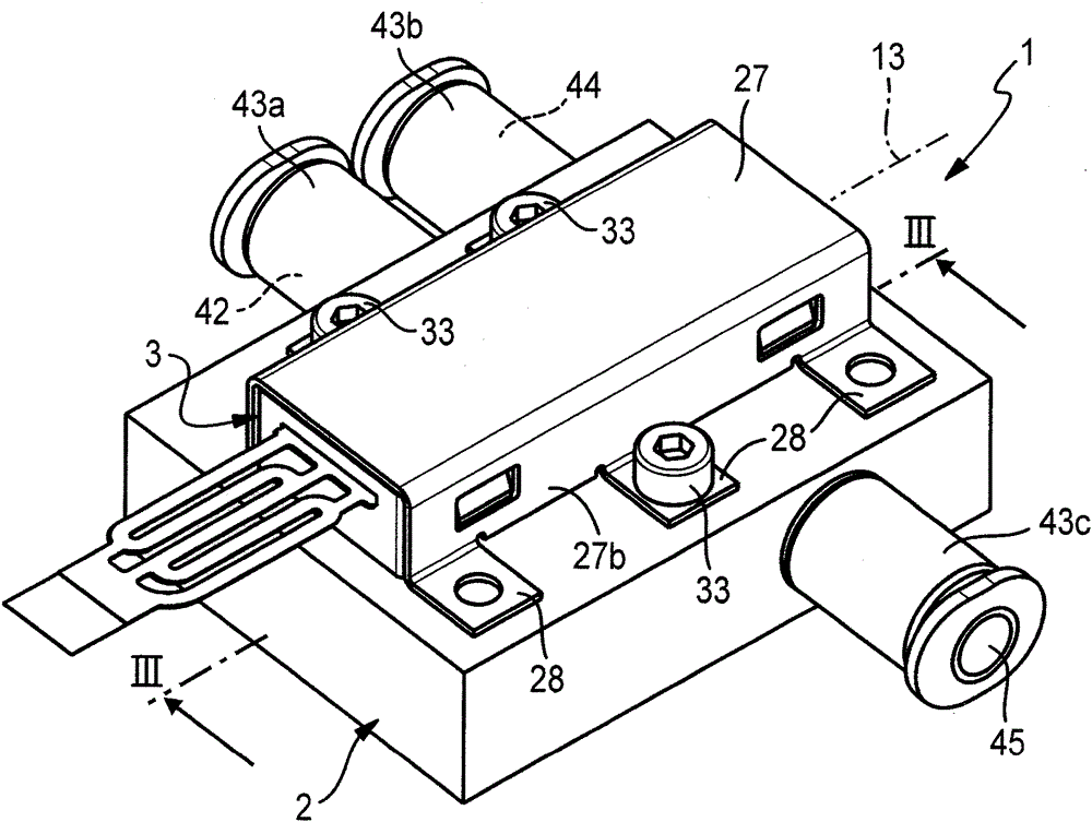
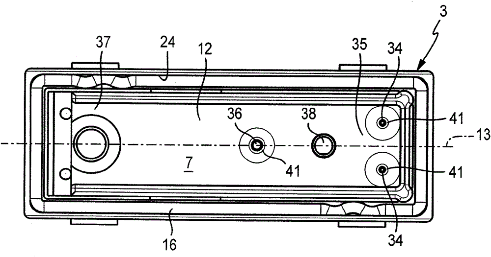
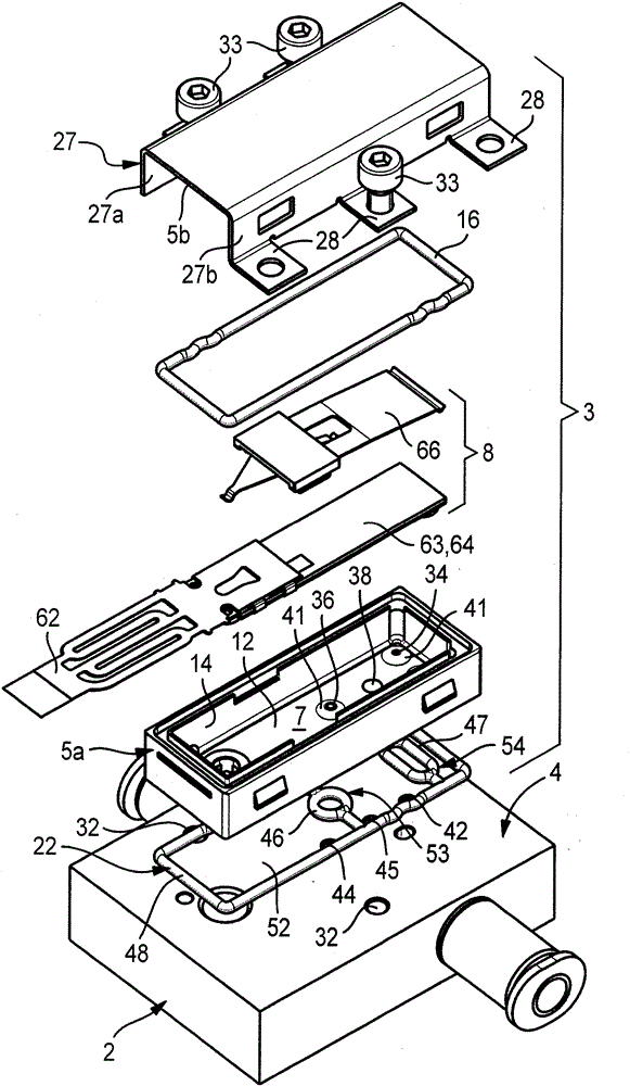
[0030] The valve assembly indicated in its entirety by the reference numeral 1 comprises in this embodiment a valve carrier 2 and a fitting surface (Bestückungsflöche) 4 which can be mounted on the valve carrier 2 and is formed by figure 1 and 3 In the visible use position the actually assembled valve 3 is also shown. The valve 3 has a valve housing, generally designated with the reference numeral 5 , which has a housing wall 6 , which surrounds a hollow space forming the valve chamber 7 , which preferably consists of plastic material.

[0031] In the valve chamber 7 there is a fluid control device 8 which is preferably designed to be electrically actuatable and which in the exemplary embodiment is of piezoelectric construction. The fluid flow of a fluid pressure medium, in particular compressed air, can be controlled through the various fluid channels by means of the fluid control device 8 .

[0032] The housing wall 6 is preferably configured as a box. It contains a wall ...


PUM


Abstract

A valve arrangement (1) is proposed which has a valve (3), in which a valve chamber (7) is formed. The valve chamber (7) is delimited by a valve seat wall (12) which supports a plurality of valve seats (41) and is penetrated by a work duct (38), to which a consumer can be connected. The work duct (38) communicates with a compensation chamber (52) which is arranged on that side of the valve seat wall (12) which lies opposite to the valve chamber (7), with the result that the valve seat wall (12) is pressure-equalized with regard to its loading and high functional precision of the valve arrangement is ensured.

Description

technical field [0001] The invention relates to a valve assembly with a valve having a housing wall surrounding a valve chamber, the housing wall having a valve seat wall with at least one supply channel and at least one relief channel (Entlastungskanal) valve seat arranged at its inner side facing the valve chamber, wherein a fluid control device is arranged in the valve chamber, which can selectively block or open the at least one supply channel and The at least one relief channel and the working channel, which opens into the valve chamber and is permanently in fluid connection with the valve chamber, extend in the housing wall. Background technique [0002] A valve assembly of this type known from EP 1564464 B1 comprises a valve with a valve housing, the housing wall of which surrounds a valve chamber in which a piezoelectric fluid control device is arranged. The fluid control device contains piezoelectric bending transducers, which can control the fluid path through a s...

Claims


Application Information

Patent Timeline
Patent Type & Authority Patents(China)
IPC IPC(8): F16K31/00F15B13/08
CPCF16K31/006F15B13/0405
Inventor G.帕莱莫J.安德勒
Owner FESTO AG & CO KG
Learn More