
Positioning pin ejection jig

A technology of positioning pins and jigs, applied in hand-held tools, manufacturing tools, etc., can solve the problems of product waste, high cost, loss, etc., and achieve the effects of convenient use, simple structure, and low cost

Inactive Publication Date: 2014-07-30
柳州优顺机械制造有限公司
View PDF8 Cites 17 Cited by
  • Summary
  • Abstract
  • Description
  • Claims
  • Application Information

AI Technical Summary

Problems solved by technology

[0002] At present, in most manufacturers, the cost of a large part of the products produced is very high, and the cost of these products is relatively high. If the positioning pins installed on the products are not good and cannot be taken out, the products with high cost will be wasted. The auxiliary fixture is easy to damage the product when taking out the positioning pin, resulting in unusable consequences and resulting in losses

Method used


Image

  • Positioning pin ejection jig

Examples


Embodiment Construction

[0013] Specific embodiments of the present invention will be further described in detail below.

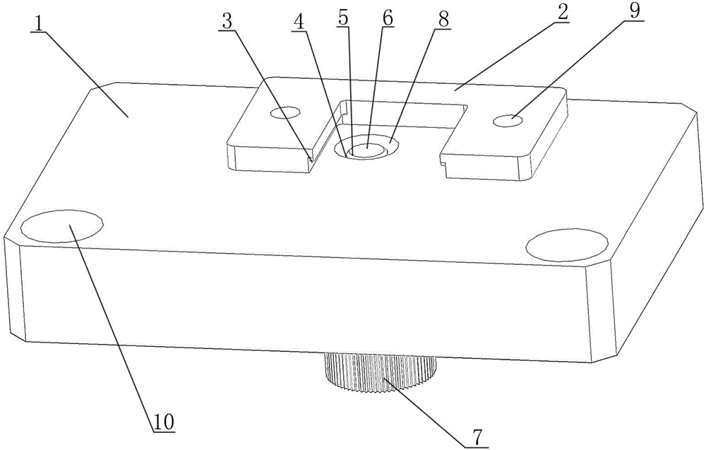
[0014] Such as figure 1 As shown, a positioning pin ejection jig of the present invention includes a rectangular block-shaped jig body 1, one end of the jig body 1 is provided with a "concave"-shaped fixing block 2, and the two inner sides of the "concave"-shaped fixing block 2 Card slots 3 are respectively provided, and a threaded through hole 4 is also provided on the fixture main body 1 between the two card slots 3 .

[0015] The threaded through hole 4 is provided with a screw 5 that matches the threaded through hole 4, the head of the screw 5 includes a top post 6, the bottom of the screw 5 is also screwed with a knob 7, and the upper end of the threaded through hole 4 includes an upper The large and small cone-shaped smooth surface 8, the two ends of the "concave"-shaped fixed block 2 are respectively provided with mounting holes 9, the "concave"-shaped fixed block 2 is det...


PUM


Abstract

The invention discloses a positioning pin ejection jig which comprises a rectangular block-shaped jig main body, and is characterized in that a fixed block which is shaped like a Chinese character ao is arranged at one end of the jig main body; clamping slots are respectively formed in two inner sides of the fixed block which is shaped like the Chinese character ao; a threaded through hole is also formed between the two clamping slots in the jig main body. The fixed block which is shaped like the Chinese character ao is used for placing a product connected with a positioning pin; the clamping slots are used for fixing the product; the threaded through hole formed between the two clamping slots in the jig main body is used for placing a screw capable of ejecting the positioning pin; an ejection column on the head of the screw is used for ejecting the positioning pin; a knob spirally connected with the lower part of the screw can control the screw to move up and down; due to a conically columnar smooth surface which is included in the upper end of the threaded through hole and is provided with a larger upper part and a smaller lower part, accidental damage to the product is avoided; the fixed block which is shaped like the Chinese character ao can be flexibly replaced; positioning holes are used for fixing the jig main body. The positioning pin ejection jig has the advantages of simple structure, convenience in use, low cost and the like.

Description

technical field [0001] The invention relates to an auxiliary jig, in particular to a positioning pin ejection jig. Background technique [0002] At present, in most manufacturers, the cost of a large part of the products produced is very high, and the cost of these products is relatively high. If the positioning pins installed on the products are not good and cannot be taken out, the products with high cost will be wasted. The auxiliary fixture is easy to damage the product when the positioning pin is taken out, resulting in unusable consequences and resulting in losses. [0003] Contents of the invention [0004] In order to overcome the above problems, the present invention provides a positioning pin ejection jig with simple structure and convenient use. [0005] The technical solution of the present invention is to provide a positioning pin ejection jig, which includes a rectangular block-shaped jig body, and is characterized in that: one end of the jig body is provid...

Claims


Application Information

Patent Timeline
Patent Type & Authority Applications(China)
IPC IPC(8): B25B27/02
CPCB25B27/023
Inventor 周建荣
Owner 柳州优顺机械制造有限公司
Learn More