Coiled tubing flush ignition device

A technology of ignition device and tubing, which is applied in wellbore/well components, production fluid, earthwork drilling and production, etc. It can solve problems such as economic loss, delay of operation period, and inability to determine whether the tubing is clean, so as to reduce pollution and improve success rate effect

Inactive Publication Date: 2017-01-11
CHINA NAT OFFSHORE OIL CORP +1
View PDF8 Cites 0 Cited by
  • Summary
  • Abstract
  • Description
  • Claims
  • Application Information

AI Technical Summary

Problems solved by technology

However, if there is a blockage in the tubing or the blockage buries the ignition head, the coiled tubing rod may not pass through the blockage, and the ignition rod cannot trigger the ignition head, resulting in perforation failure. At this time, it is often necessary to pull out the perforation equipment again
Perforation failure is a major accident in the workover operation process, which not only delays the operation period and causes economic losses, but also leads to major safety hazards when untriggered perforating equipment is lifted to the ground and disassembled
Therefore, on the premise that it is impossible to determine whether the oil pipe is clean, the ignition method of coiled tubing rod casting is generally used with caution on site.
[0003] In order to solve this problem, for high-inclination wells, positive pressure ignition is usually implemented by applying hydraulic pressure in the tubing. However, although this ignition method ensures the success rate of perforation, it will cause relatively large oil and gas formations at the moment of ignition. The large positive pressure difference causes the liquid in the wellbore and the debris generated during the perforation process to enter the formation, causing secondary pollution after perforation and reducing the perforation effect, especially for low-pressure oil and gas wells, the pollution will be more serious

Method used


Image

  • Coiled tubing flush ignition device
  • Coiled tubing flush ignition device
  • Coiled tubing flush ignition device

Examples


Embodiment Construction

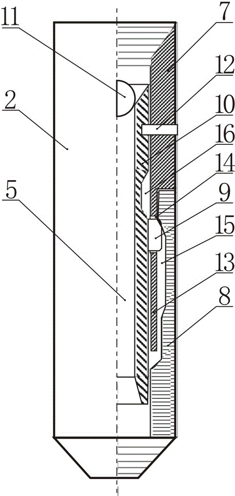
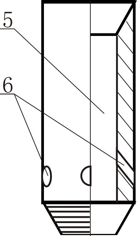
[0018] Such as figure 1 , 2 As shown, the coiled tubing flushing and ignition device is composed of a tubing joint 1, a ball-pitching shear separation component 2, a flushing pipe 3 and an ignition rod 4. , one end of the flushing pipe 3 is threadedly connected to the tubular lower joint of the ball-pitching-shearing separation assembly 2, and the other end is threadedly connected to the ignition rod 4, and the oil pipe joint, the ball-pitching-shearing separation assembly, and the flushing pipe are respectively provided with interconnected flushing liquids channel 5, the wall of the flushing pipe 3 is provided with a flushing hole 6 communicating with the flushing liquid passage 5; A ball seat 10, a steel ball 11 and a pin 12 are formed. The tubular insertion part 13 at the lower end of the tubular upper joint 7 is inserted into the upper port of the tubular lower joint 8. The left pipe wall and the right side of the tubular insertion part 13 are The side tube walls are res...


PUM


Abstract

The invention discloses a flushing and ignition device for a continuous oil pipe. The flushing and ignition device comprises an oil pipe joint, a pitching shear separation type component, a flushing pipe and an ignition rod, wherein the oil pipe joint is connected to a tubular upper joint of the pitching shear separation type component, one end of the flushing pipe is connected to a tubular lower joint of the pitching shear separation type component, the other end of the flushing pipe is connected to the ignition rod, flushing fluid channels, which are communicated with each other, are respectively arranged in the oil pipe joint, the pitching shear separation type component and the flushing pipe, and flushing holes, which are communicated with the flushing fluid channels, are formed in the walls of the flushing pipe; the pitching shear separation type component is formed by the tubular upper joint, the tubular lower joint, a locking piece, a tubular ball seat, a steel ball and a pin. By adopting the structural form, the success rate of mechanical ignition of the continuous oil pipe is improved, and the pollution of a perforated section due to too long soaking time of borehole fluid after perforation is reduced. The flushing and ignition device has the functions of flushing, ignition, gas lifting induced flow and separation after the flushing and ignition device is blocked.

Description

technical field [0001] The invention relates to the technical field of offshore oilfield engineering, in particular to a coiled tubing flushing and ignition device. Background technique [0002] At present, in the perforation operation of offshore well completion and workover, hydraulic ignition and coiled tubing rod ignition are mainly used for triggering perforating guns in highly deviated wells. Coiled tubing rod ignition can realize negative pressure perforation and avoid perforation Secondary pollution in the process. When the oil pipe is relatively clean and there is no blockage such as oil sludge and iron filings, the purpose of ignition can be achieved by using coiled tubing to throw rods. However, if there is a blockage in the tubing or the blockage buries the ignition head, the coiled tubing rod may not pass through the blockage, and the ignition rod cannot trigger the ignition head, resulting in perforation failure. At this time, it is often necessary to pull out...

Claims


Application Information

Patent Timeline
Patent Type & Authority Patents(China)
IPC IPC(8): E21B43/1185
Inventor 于东谢金秋范远洪颜明廖云虎谢思宇梁玉凯于志刚贾辉
Owner CHINA NAT OFFSHORE OIL CORP
Why Eureka
Try Eureka