Fire adjustment device

An adjustment device and firepower technology, applied in the field of firepower adjustment devices, can solve the problems of large-scale motors, increased power consumption, and increased motor costs, and achieve the effects of miniaturization, prevention of ignition failure, and reduction of power consumption

Active Publication Date: 2018-06-29
RINNAI CORP
View PDF5 Cites 0 Cited by
  • Summary
  • Abstract
  • Description
  • Claims
  • Application Information

AI Technical Summary

Problems solved by technology

[0011] For the device for opening the valve of the electromagnetic safety valve with an electric motor as shown in Patent Document 1 in the above-mentioned existing fire power adjustment device, since the valve opening of the electromagnetic safety valve requires a large torque, the size of the motor is therefore increased.
However, the increase in the size of the motor not only increases the cost of the motor but also increases power consumption. Therefore, there is a disadvantage that the life of the battery is shortened especially when the battery is used as the power source for driving.
[0012] On the other hand, although the device for manually performing the ignition operation as shown in the above-mentioned Patent Document 2 does not need a power source, the push force acting on the operating knob does not directly act on the connecting rod, but acts on the connecting rod through indirect components. The connecting rod, therefore, the pushing force acting on the operating knob is not all acting on the connecting rod, thus, the required pushing force becomes larger, which not only makes the pushing difficult but also because the pushing force acts on the connecting rod. Therefore, it may not be possible to reliably press the movable iron piece connected to the valve body of the electromagnetic safety valve against the magnetic pole of the electromagnet.
In addition, if the movable iron piece connected to the valve body cannot be reliably pressed against the magnetic pole of the electromagnet, the movable iron piece cannot be adsorbed and held even if a holding current is passed through the electromagnet to excite the magnetic pole, resulting in combustion. The case where the device cannot be ignited

Method used


Image

  • Fire adjustment device
  • Fire adjustment device
  • Fire adjustment device

Examples


Embodiment Construction

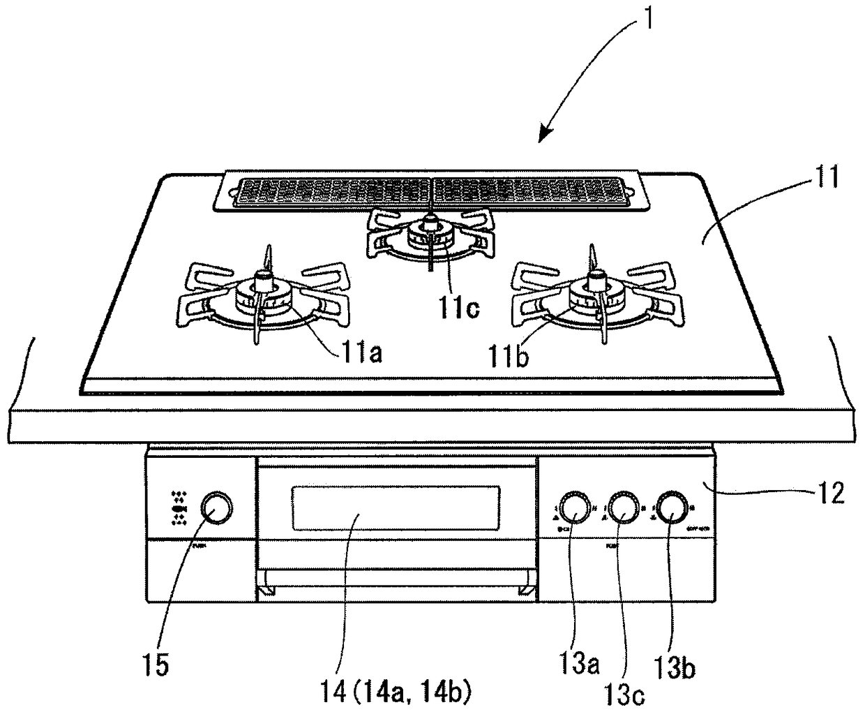
[0052] refer to figure 1 , No. 1 is a gas stove suitable for the fire power regulating device of the present invention. A top plate 11 is arranged on the upper surface of the gas stove 1, and three gas burners 11a, 11b, 11c are arranged on the top plate 11. On the front panel 12 of the gas stove 1, there are fire power adjustment devices 13a, 13b, 13c for igniting, extinguishing and fire power adjustment of each gas burner 11a, 11b, 11c. In addition, a grill cabinet 14 is provided approximately at the center of the front panel 12 , and an upper burner 14 a and a lower burner 14 b are provided in the grill cabinet 14 . In addition, the ignition, extinguishment, and adjustment of the heating power of the upper burner 14 a and the lower burner 14 b are performed by the heating power adjusting device 15 .

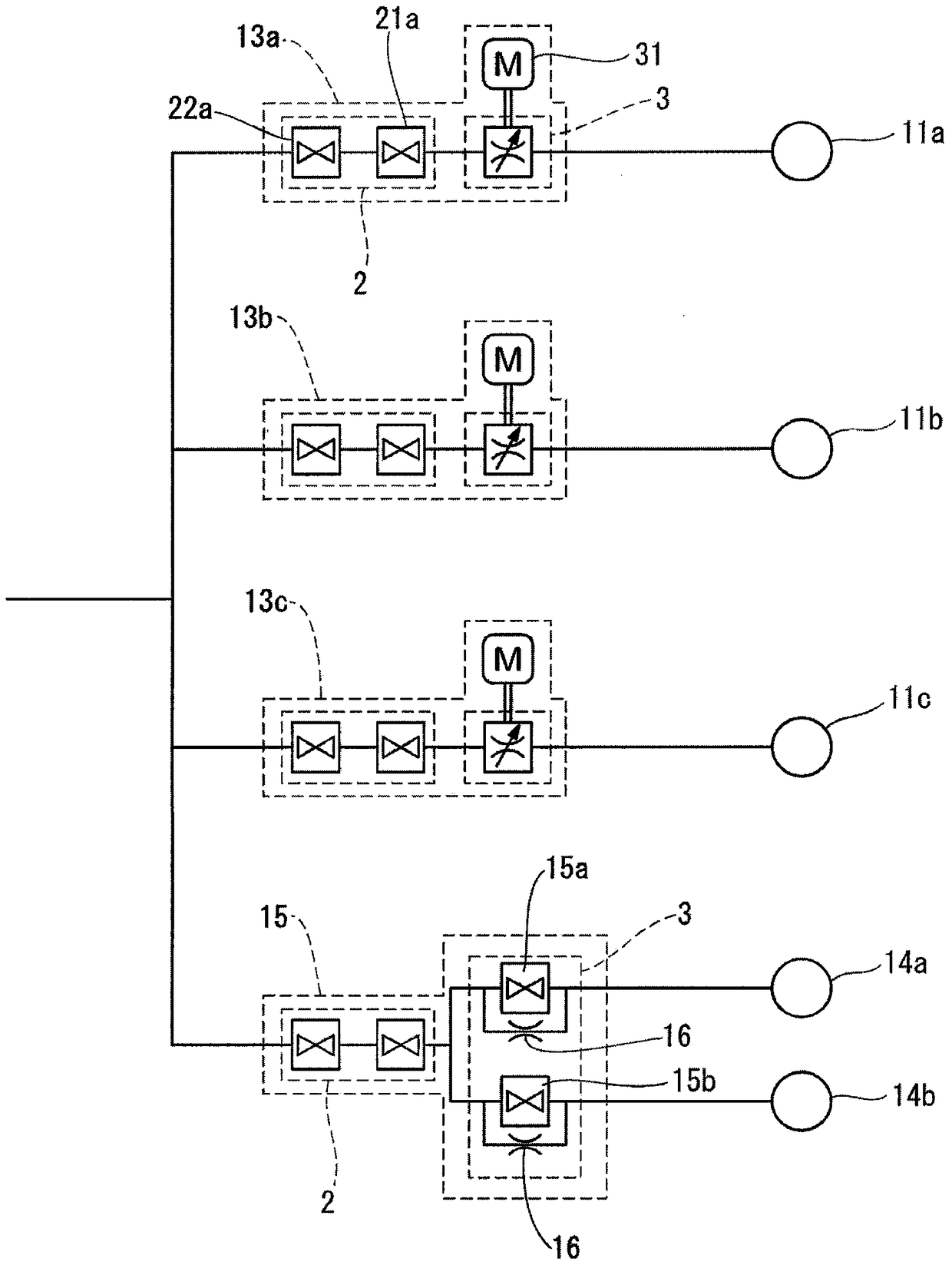
[0053] refer to figure 2 , in the present embodiment, the gas supply pipeline is separated into four that are arranged in parallel, and the fire power adjustment devices 13a...


PUM


Abstract

In a manually operated traditional heat intensity adjusting device, all pressure applied to an operation handle does not act on a rod as the pressure applied to the operation handle does not act directly on the rod but acts on the rod via an indirect member. Therefore, higher pressure is needed. In addition, a valve body of an electronic safety valve cannot be firmly pressure-attached to an electromagnet inside the electronic safety valve as the pressure acts in a direction different from the moving direction of the rod. The rod and the electronic safety valve are installed behind the operation handle and a movable iron piece connected to the valve body of the electronic safety valve is pressure-attached to the stimulus of the electromagnet of the electronic safety valve by pressure on the operation handle. Moreover, an electric device can be miniaturized, and power consumption can be reduced as only heat intensity is electrically adjusted.

Description

technical field [0001] The invention relates to a fire power adjusting device capable of igniting a burner by pushing an operation knob and turning the operation knob to adjust the fire power. Background technique [0002] The ignition, flameout and firepower adjustment of the gas stove are carried out through the ignition and flameout buttons and the firepower adjustment knob etc. arranged on the front panel of the gas stove. In the existing gas cooker, these ignition, flameout buttons and firepower adjustment knobs are set separately, however, these ignition, flameout buttons and firepower adjustment knobs are integrated into one operation knob in response to the requirements of appearance design, and are pushed and pressed respectively. A gas cooker is also known in which a burner is ignited by operating a knob and the heating power of the gas cooker is adjusted by turning the knob (see, for example, Patent Document 1). [0003] In this kind of gas cooker, the operation ...

Claims


Application Information

Patent Timeline
Patent Type & Authority Patents(China)
IPC IPC(8): F23N1/00
CPCF23N5/26F24C3/12
Inventor 近藤秀幸林雄一野野山昌生
Owner RINNAI CORP
Why Eureka
Try Eureka