Experimental device and experimental method for simulating dynamic leakage and leaking stoppage of drilling fluid

An experimental device and drilling fluid technology, applied in earthwork drilling, wellbore/well components, measurement, etc., can solve problems such as inability to use simulation, inability to simulate leakage phenomena well, ignoring drilling fluid flow, etc., and achieve experimental error Small size, easy operation, large core size effect

Inactive Publication Date: 2014-07-30
CHINA UNIV OF PETROLEUM (EAST CHINA)
View PDF8 Cites 19 Cited by
  • Summary
  • Abstract
  • Description
  • Claims
  • Application Information

AI Technical Summary

Problems solved by technology

[0002] The lost circulation problem in the process of oil and gas drilling has always been a major engineering technical problem that plagues oil exploration and development at home and abroad, and has not been completely resolved so far.
For example, the simulated crack plugging test device and test method published by the invention patent application number 200910167764.9 and the high-temperature and high-pressure drilling fluid loss dynamic evaluation instrument published by the invention patent application number 201210023152.4 all use stainless steel plates to simulate cracks, which cannot be used for The simulation of the actual core, and only s

Method used


Image

  • Experimental device and experimental method for simulating dynamic leakage and leaking stoppage of drilling fluid
  • Experimental device and experimental method for simulating dynamic leakage and leaking stoppage of drilling fluid
  • Experimental device and experimental method for simulating dynamic leakage and leaking stoppage of drilling fluid

Examples


Embodiment Construction

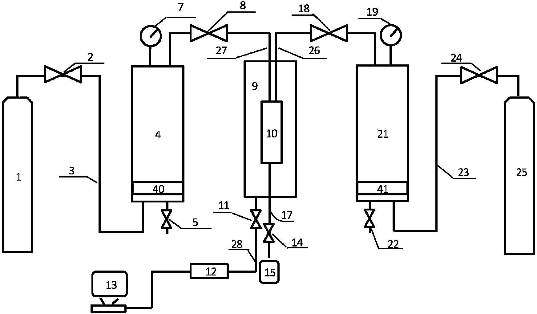
[0033] Such as figure 1 As shown, the experimental device for simulating the dynamic loss and plugging of drilling fluid includes: a first high-pressure nitrogen cylinder 1, a first circulation cylinder 4, a loss test cylinder 9, a core holder 10, a second circulation cylinder 21, and a second high-pressure nitrogen cylinder. A nitrogen cylinder 25, a servo-controlled injection pump 12; a core holder 10 is placed in the leakage test cylinder 9.

[0034] The first high-pressure nitrogen cylinder 1 is connected to the bottom end of the first circulation cylinder 4 through the first high-pressure pipeline 3, and the first pressure-reducing valve 2 is set on the first high-pressure pipeline 3; high-pressure nitrogen is housed in the first high-pressure nitrogen cylinder 1, with To provide pressure to the drilling fluid in the first circulation cylinder 4; the first piston 40 is provided in the first circulation cylinder 4, and the first piston 40 is used to realize the isolation o...


PUM


Abstract

The invention belongs to the field of petroleum engineering, and particularly relates to an experimental device and an experimental method for simulating dynamic leakage and leaking stoppage of drilling fluid. The experimental device for simulating the dynamic leakage and leaking stoppage of the drilling fluid comprises a first high-pressure nitrogen bottle, a first circulating cylinder, a leakage test cylinder, a second circulating cylinder, a second high-pressure nitrogen bottle and a servo control injection pump, wherein the first high-pressure nitrogen bottle is connected with the bottom end of the first circulating cylinder; the two ends of a fifth high-pressure pipeline are respectively connected with the upper end of the first circulating cylinder and the upper end of a rock core clamping device; the servo control injection pump is connected with the lower end of the leakage test cylinder; the second high-pressure nitrogen bottle is connected with the bottom end of the second circulating cylinder; the two ends of a fourth high-pressure pipeline are respectively connected with the upper end of the second circulating cylinder and the upper end of the rock core clamping device. According to the experimental device and the experimental method, the positive circulating and positive circulating dynamic leaking stoppage processes of the drilling fluid on the end surfaces of rock cores with different lithological characters in an original crustal stress state can be really simulated; the simulated rock core size is large; the experimental method is simple; the experimental error is small; the experimental device and the experimental method have higher guidance value to field application.

Description

technical field [0001] The invention belongs to the field of petroleum engineering, and in particular relates to an experimental device and an experimental method for simulating the dynamic leakage and plugging of drilling fluid, which are used for the prediction of leakage pressure and the plugging of corresponding plugging agents when oil drilling encounters leaky formations. Leakage effect evaluation. Background technique [0002] The lost circulation problem in the process of oil and gas drilling has always been a major engineering technical problem that plagues oil exploration and development at home and abroad, and has not been completely resolved so far. The wall leakage will not only cause a series of complex situations such as pipe sticking, blowout, and collapse, but also increase the cost of drilling, and also bring great difficulties to the later development. Along with the deep development of oil field, the increase of deep well, ultra-deep well and complex wel...

Claims


Application Information

Patent Timeline
IPC IPC(8): E21B47/10E21B33/13
Inventor 韩忠英程远方常鑫邓文彪徐鹏
Owner CHINA UNIV OF PETROLEUM (EAST CHINA)
Why Eureka
Try Eureka