
Method and device for implementing the same

A technology of impact head and back groove, which is applied in the direction of driving devices, earthwork drilling, cutting machinery, etc., and can solve problems such as damage to the impact power box, large contact area with materials, and equipment that cannot work continuously

Active Publication Date: 2020-07-10
刘素华
View PDF8 Cites 0 Cited by
  • Summary
  • Abstract
  • Description
  • Claims
  • Application Information

AI Technical Summary

Problems solved by technology

For example, the reciprocating impact shearer must have a certain amount of undercover excavation in order to match the flexible scraper conveyor used for reloading, and it must also have sufficient top cutting in order to facilitate the smooth advancement of the hydraulic support. Therefore, the impact head must be set There is a certain height, that is, the impact head must be made larger and heavier, but when the larger and heavier impact head hits the material, it will contact the material with a large area at one time, so that the reaction force is concentrated and strong, and the impact reaction force is transmitted to the guide mechanism, The driving mechanism and the rear of the fuselage are easy to damage the guiding mechanism and the driving mechanism, prematurely damage the impact power box, etc., and easily cause the impact reaction force to resonate with the fuselage to deform the fuselage. Serious losses caused by the inability of the equipment to work continuously. In order to solve the above-mentioned problems, the present invention proposes a method of increasing and / or widening the back groove to straighten the impact head and implementing the method by using the heightening and / or widening of the back groove Righting the impact head device, which greatly reduces the height and / or width of a single impact head, realizes the purpose of mining lower materials by a single impact head and combining multiple smaller impact heads to use the same power source, saving energy and reducing consumption and improving efficiency

Method used


Image

  • Method and device for implementing the same
  • Method and device for implementing the same
  • Method and device for implementing the same

Examples


Embodiment 1

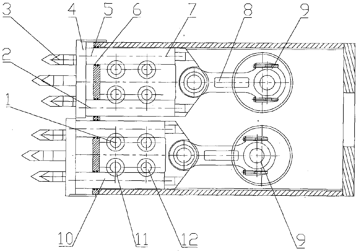
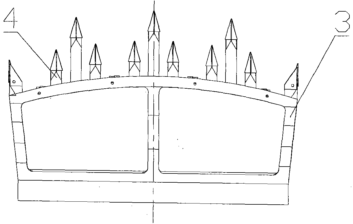
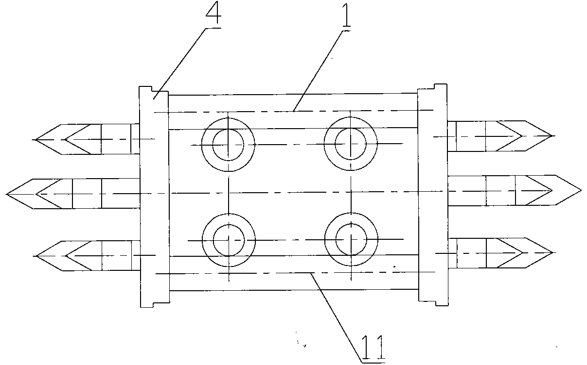
[0088] figure 1 To Fig. 4 is the method for increasing and / or widening the righting impact head with the back groove and the method for implementing the method in embodiment 1. The use of the back groove to increase and / or widen the righting impact head device, the use of the back groove to increase And / or the widening and righting impact head device comprises opposite back groove guide mechanism 37, impact supporting mechanism 12, driving mechanism 9, impact head 3 etc., and impact head 3 comprises gear seat 4 etc., and opposite back groove guide mechanism 37 comprises rolling friction pair The back groove structure 10, the impact guide 7, etc., the rolling friction pair back groove structure 10 includes an upper rolling friction groove 1, a lower rolling friction groove 11, etc., and the upper rolling friction groove 1 and the lower rolling friction groove 11 include guide rolling friction body 6, etc., the impact guide 7 includes an upper impact guide 5, a lower impact guid...

Embodiment 2

[0106] Figure 5 It is the heightening and / or widening centering impact head device described in Embodiment 2. The difference from Embodiment 1 is that the upper arc-shaped rolling friction groove 13 and the lower arc-shaped rolling friction groove 14 are arranged on the gear seat 4 In the U-shaped guide frame 15 formed with the upper impact guide 5 and the lower impact guide 2 or in the frame-shaped guide frame 38 or cylindrical guide frame, the tooth seat 4 will correspond to the upper impact guide 5 and the lower impact guide 2. Fastened on the upper arc-shaped rolling friction groove 13, the lower arc-shaped rolling friction groove 14, etc., the power impact member 8 drives the tooth seat 4 or the upper impact guide 5, the lower impact guide 2, etc. to reciprocate, and the upper impact guide 5 , the lower impact guide 2, etc. realize rolling friction reciprocating motion under the support of the upper arc-shaped rolling friction groove 13 and the lower arc-shaped rolling f...

Embodiment 3

[0109] Figure 6 to Figure 7 For embodiment 3, the use of back groove heightening and / or widening of the righting impact head device is different from embodiment 1 in that the rolling elements 16 on the upper part of the upper impact guide 5 and the lower impact guide 2 are reduced. The rolling elements 16 etc. reduce the height of the back groove guide mechanism 37, thereby reducing the height of the gear seat 4, etc., use the back groove guide mechanism 37 to reduce the use quantity of the rolling elements 16, etc., and make a larger impact head 3 smaller Small or a single tooth seat 4 with the same impact cutting height is divided into multiple tooth seats 4, the single-layer impact head 3 with the same impact cutting height is changed to a combination of multi-layer impact heads 3, etc., each of the combined impact head 17 The small impact head 3 uses the same power source 18, etc., so that the impact area of ​​each small impact head 3 is reduced, the impact force is large...


PUM


Abstract

The utility model belongs to the field of machinery and particularly relates to a device for heightening and / or widening and correcting an impact head by using back-trough pairs, which is suitable for mining or mechanical engineering field. The device comprises a back-trough pair guide mechanism, an impact supporting mechanism, a driving mechanism, an impact head and the like, wherein the back-trough pair guide mechanism comprises a rolling friction back-trough pair structure, an impact guide element and the like, the rolling friction back-trough pair structure comprises an upper rolling friction recess and a lower rolling friction recess, a power impact element drives the impact guide element and the like to reciprocate, the impact guide element is placed in a space occupied by an external guide rolling body, the impact guide element increases the correcting height and the like of the impact head, and the rolling friction back-trough pair structure and the impact guide element correct the reciprocating movement direction of a toothholder.

Description

technical field [0001] The invention belongs to the field of machinery, and is especially applicable to a method for increasing and / or widening a backing groove to straighten an impact head in the field of mining or construction machinery and to implement the method by using a back groove to increase and / or widen a righting impact head device. Background technique [0002] Coal shearers, roadheaders, and excavators are collectively referred to as mining machines. Reciprocating impact mining machines and reciprocating impact excavators are used in the upper and lower parts of the impact guide to quickly and efficiently mine rocks or coal seams or cement concrete or hardened mudstone. Both are equipped with guide rolling bodies, because the upper and lower rolling bodies need to occupy a large space, so the size of the impact guide supporting the righting impact head is relatively reduced, resulting in insufficient strength to support the righting impact head, so that the impa...

Claims


Application Information

Patent Timeline
Patent Type & Authority Patents(China)
IPC IPC(8): E21C25/02E21C25/04E21C31/02E21C35/04E21C35/08E21C35/18
Inventor 刘素华
Owner 刘素华
Learn More