Cable paying-off device

A pay-off device and cable technology, which is applied in the installation of optical fibers/cables, cable laying equipment, and the arrangement of the use of reels/photosensitive drums, etc. The effect of labor-saving, turning labor-saving and fast construction

Active Publication Date: 2014-07-30
STATE GRID SHANDONG ELECTRIC POWER COMPANY RIZHAOPOWER SUPPLY +1
View PDF8 Cites 0 Cited by
  • Summary
  • Abstract
  • Description
  • Claims
  • Application Information

AI Technical Summary

Problems solved by technology

However, in many occasions, power take-up and pay-off is not required, only manual pay-off is required. The manual pay-off device in the prior art is relatively laborious and greatly affects the construction progress. Therefore, the construction field expects labor-saving , Easy to put the cable device

Method used


Image

  • Cable paying-off device
  • Cable paying-off device
  • Cable paying-off device

Examples


Embodiment 1

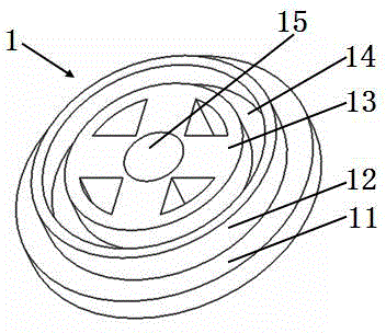
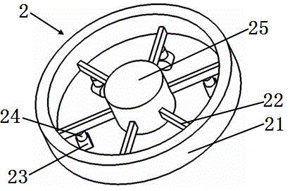
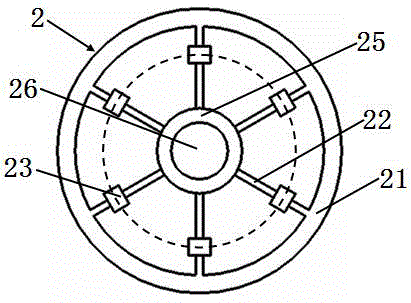
[0028] Please see Figure 1 to Figure 5 A cable pay-off device, characterized in that it includes a fixing device 1, a movable device 2 and a rotating support 3; the fixing device has a base 11, a limiting member protruding from the base and having an outer diameter smaller than the outer diameter of the base 12. A fixing seat 13 protruding from the base and having an outer diameter smaller than the inner edge diameter of the limiting member. The limiting member is located outside the fixing seat. A cylindrical annular channel 14 is formed between the limiting member and the fixing seat. The center of the fixing seat has a depression toward the base. The first groove 15; the movable device has a cylindrical ring bracket 21 located on the outer layer, a shaft hole positioning column 25 located in the center, six bearing rods 22 connecting the cylindrical ring bracket and the shaft hole positioning column, and each bearing rod is installed below Connecting rods 24, a sliding devic...

Embodiment 2

[0037] Please see Image 6 And refer to Figure 1 to Figure 5 , A cable pay-off device, basically the same as the first embodiment, the difference is that: the base 11 of the fixing device also has a plurality of fixing holes 16.

[0038] Further, the above-mentioned fixing holes are symmetrically distributed on the fixing device.

[0039] The existence of the fixing hole can make the fixing device be fixed on a horizontal surface, such as a soil surface, etc., so that the line and the cable are more stable.

Embodiment 3

[0041] Please see Figure 7 And refer to Figure 1 to Figure 5 , A cable pay-off device, basically the same as the first embodiment, the difference lies in: the inner side of the sliding device is installed with an inner limit device 27, the outer side of the sliding device is installed with an outer limit device 28, the inner and outer limit devices and The sliding device is non-contact, but it restricts the direction of the sliding device. It does not make the sliding device rotate 360 ​​degrees around the connecting rod, but the direction is relatively stable. In this way, when the movable device is started, the cable is more labor-saving, because All sliding devices move in one direction.

[0042] Implementation example 3

[0043] Please see Figure 7 And refer to Figure 1 to Figure 5 , A cable pay-off device, basically the same as the first embodiment, the difference lies in: the inner side of the sliding device is installed with an inner limit device 27, the outer side of t...


PUM


Abstract

The invention belongs to the technical field of power construction and cables, and particularly relates to a cable paying-off device. The cable paying-off device is characterized by comprising a fixed device (1), a movable device (2) and a rotary supporting body (3); in the installation state, the fixed device is placed on the horizontal surface, the movable device is placed above the fixed device, and the rotary supporting body is arranged between the movable device and the fixed device. The cable paying-off device has the advantages of being simple in structure, easy to install, capable of saving more labor during paying-off, and higher in paying-off speed.

Description

technical field [0001] The invention belongs to the field of electric power construction and cable technology, and in particular relates to a cable pay-off device. Background technique [0002] Wires and cables are usually coiled on the pan, and the cables are released from the pan during power construction or laying. In the existing construction technology field, power take-up and pay-off devices and manual pay-off devices are commonly used. Power deployment requires power, usually electricity from the grid or tractors to generate power for the take-up and pay-off device. However, in many occasions, power take-up and pay-off is not required, only manual pay-off is required. The manual pay-off device in the prior art is relatively laborious and greatly affects the construction progress. Therefore, the construction field expects labor-saving , Easy to put the cable device. Contents of the invention [0003] In order to solve the above problems, the present invention disc...

Claims


Application Information

Patent Timeline
Patent Type & Authority Applications(China)
IPC IPC(8): H02G11/02
CPCG02B6/46H02G1/06
Inventor 戴丽芬
Owner STATE GRID SHANDONG ELECTRIC POWER COMPANY RIZHAOPOWER SUPPLY
Why Eureka
Try Eureka