

Monitoring equipment lens ITO heating and de-icing device
A technology for monitoring equipment and lenses, applied to heating element materials, TVs, color TV parts, etc., can solve the problems of poor deicing effect on the surface of equipment, large heating space, slow heating process, etc., and achieve good dew removal effect , Small heating space, fast heating process
Inactive Publication Date: 2014-07-30
徐继胜
View PDF7 Cites 16 Cited by
- Summary
- Abstract
- Description
- Claims
- Application Information
AI Technical Summary
Problems solved by technology
Its disadvantages are: 1. When heating, it must conduct heat through the metal parts of the equipment, and then conduct it to the transparent cover or transparent glass window, and the heating process is slow
2. The heating space is relatively large. When heating, the internal heating of the entire monitoring equipment must be conducted to the surface of the equipment, resulting in poor deicing effect on the surface of the equipment.
Method used
View moreImage
Smart ImageViewing Examples

Examples
Embodiment Construction
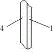
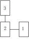
[0011] Referring to the accompanying drawings, the present invention is an ITO heating and deicing device for a monitoring equipment lens, including a monitoring equipment lens (4), characterized in that: there is a layer of ITO transparent conductive film (1) on the outer surface of the monitoring equipment lens (4) The resistance composed of the ITO transparent conductive film is connected to the temperature control circuit (2), and the temperature control circuit (2) is connected to the temperature sensor (3).
Login to View More PUM
 Abstract
A monitoring equipment lens ITO heating and de-icing device comprises a monitoring equipment lens (4) and is characterized in that a layer of resistor composed of an ITO transparent conductive film (1) is arranged on the outer surface of the monitoring equipment lens (4), the resistor composed of the ITO transparent conductive film is connected with a temperature control circuit (2), and the temperature control circuit (2) is connected with a temperature sensor (3). The device has the advantages that the monitoring equipment lens can be de-iced quickly or the surface of the monitoring equipment lens is prevented from icing, heating is quick, heating space is small, and the de-icing effect and the de-dewing effect are good.
Description
technical field [0001] The invention relates to a monitoring device, relates to an ITO and a deicing device, in particular to an ITO heating and deicing device for the lens of the monitoring device. Background technique [0002] The monitoring equipment works in the outdoor open-air place. When the ambient temperature is low, the lens will fog or freeze, resulting in unclear images and affecting the monitoring effect. Therefore, the monitoring equipment is required to have a heating and deicing device for the lens. The lens heating and deicing device of monitoring equipment in the prior art is generally completed by a heating resistor or a piece of heating silicon chip combined with an automatic control circuit. Eliminate or prevent the phenomenon of icing and fogging on the lens surface of monitoring equipment. Its disadvantages are: 1. When heating, it must conduct heat through the metal parts of the equipment, and then conduct it to the transparent cover or transparent g...
Claims
Login to View More Application Information
Patent Timeline
 Patent Type & AuthorityApplications(China)
IPC IPC(8): H04N5/225H05B3/10
Inventor徐继胜
Owner徐继胜