Position adjustment device of steering wheel

A technology of adjusting device and steering wheel, applied in steering column, steering control, steering mechanism, etc., can solve problems such as operator discomfort

Active Publication Date: 2014-07-30
NSK LTD
View PDF9 Cites 10 Cited by
  • Summary
  • Abstract
  • Description
  • Claims
  • Application Information

AI Technical Summary

Problems solved by technology

As a result of these, when operating the adjustment lever 14, it may cause discomfort to the operator.

Method used


Image

  • Position adjustment device of steering wheel
  • Position adjustment device of steering wheel
  • Position adjustment device of steering wheel

Examples


Embodiment Construction

[0052] "First example of embodiment"

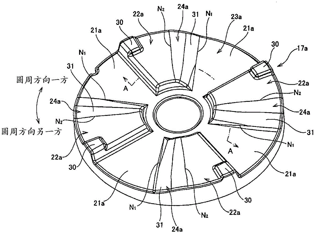
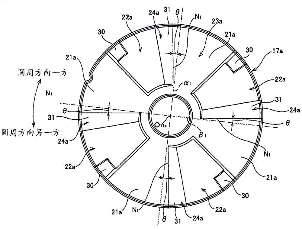
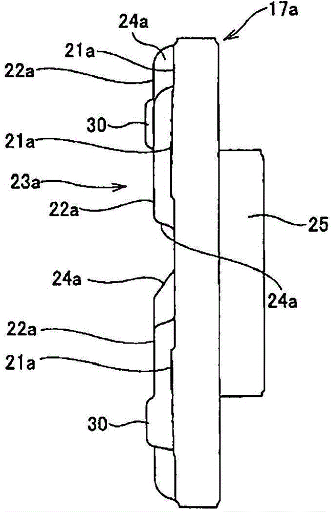
[0053] Figure 1 to Figure 8The first example of the embodiment of the present invention is shown. The steering wheel position adjusting device of the present invention includes a steering shaft 1, a steering column 2, a vehicle body side bracket 5, a rod member 12, a cam device 15, a nut 13 as a pressing member, and an adjustment rod 14 (refer to Figure 13 and Figure 14 ).

[0054] A steering wheel (not shown) is fixed to the rear end portion of the steering shaft 1 . The steering column 2 rotatably supports a steering shaft inside. A displacement bracket 9 serving as a bracket on the column side is fixed to an axially intermediate portion of the steering column 2 . The displacement bracket 9 is obtained by bending a metal plate, has a substantially U-shaped cross section, and is fixed to the axially intermediate portion of the steering column 2 by welding or the like. The displacement bracket 9 is equipped with a pair of clamped...


PUM


Abstract

Provided is a position adjustment device of steering wheel such that, during an operation for holding a steering wheel at a position after adjustment, operation torque applied to an adjustment lever (14) in the first half of the operation can be decreased while improved operability can be obtained. During a transition from a state in which the steering wheel position can be adjusted to a state in which the position can be held, a portion of a drive-side cam face (20a) that is configured to slidingly contact a driven-side continuous face (24a)(sliding-contact portion virtual line M) is inclined toward one circumferential direction with respect to one circumferential end (N1) of the driven-side continuous face (24a), with the portion being superposed on the one circumferential end (N1) of the driven-side continuous face (24a). Therefore, the sliding contact portion between the drive-side cam face (20a) and the driven-side continuous face (24a) gradually increases from a radial inner end toward radially outside during the operation.

Description

technical field [0001] The present invention relates to a position adjustment device for a steering wheel capable of adjusting the up-down position or the front-back position of the steering wheel of a motor vehicle. Specifically, it relates to the structure of a cam device provided on the steering wheel position adjusting device for holding and releasing the steering wheel position. Background technique [0002] As a device for adjusting the height position of the steering wheel according to the driver's physique, driving posture, etc., there are described in Japanese Patent Application Laid-Open No. 2009-227181, Japanese Patent Laid-Open No. 2010-254159, and Japanese Patent Laid-Open No. Tilt steering device in gazette, etc. Figure 13 to Figure 16 An example of a conventional configuration of a tilt steering device is shown. This tilt steering device has a Figure 13 The steering shaft 1 is rotatable by a steering wheel (not shown) at the right end of the body), and the...

Claims


Application Information

Patent Timeline
Patent Type & Authority Applications(China)
IPC IPC(8): B62D1/18F16H25/12
CPCB62D1/184B62D1/185B62D1/189F16H25/186
Inventor 三原伸服部广行
Owner NSK LTD
Why Eureka
Try Eureka